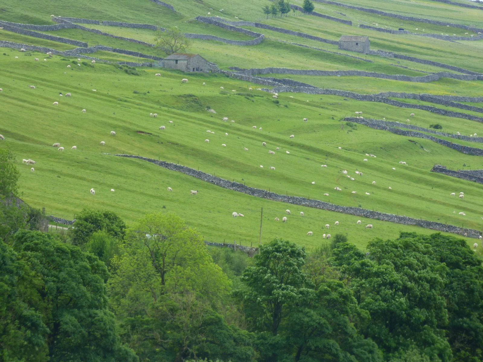
Galicia
The region of Galicia, located in the northwest of the Iberian Peninsula, has a history that stretches back to prehistoric Read more
Syncretism through the ages
Syncretism, the amalgamation of different religions, cultures, or schools of thought, has its roots in the ancient world.
Brigantes in Arthurian Legend
Brigantia, Cartimandua and Gwenhwyfar by Michelle Ziegler, Belleville, Illinois The name Brigantia represents three separate concepts: a goddess, a people, Read more
The hero archetype
At its core the “hero” is the figure who steps out of ordinary society, confronts chaos or a monster, and returns (or dies) having secured order for the group. In Jungian and comparative-myth terms it sits in the “warrior-champion” slot of the collective story-board; evolutionists would say it crystallises the survival value of decisive coalition leadership in small bands.
Earliest visual hints of a heroic idea
Scholars and archaeologists have noticed that from very early dates, hunting scenes can often show attention to heroic acts, and the have suggested that such scenes may well be an origination point for a later, more well defined hero archetype.
| Date (BP) |
Object / scene |
Why scholars read it as “proto-heroic” |
Source |
| 40 000–35 000 |
Lion-Man of Hohlenstein-Stadel – mammoth-ivory figure, human body + cave-lion head, 31 cm high |
Combines human agency with the apex predator; plausibly a master-of-beasts or shaman-hero rather than a fertility idol. |
(Wikipedia) |
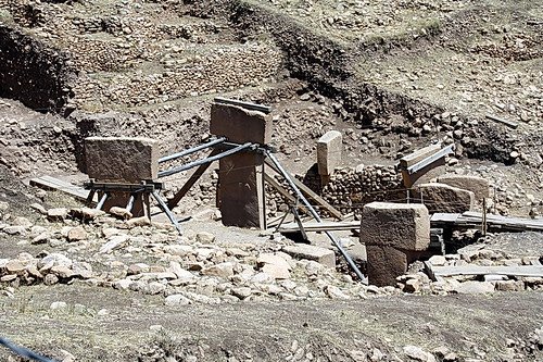
| 11 600–11 000 |
Göbekli Tepe, Pillar 43 – relief shows a decapitated man amid dangerous beasts |
One of the first narrative carvings of a human confronting lethal animals; interpreters (e.g., Notroff 2016) see a mythic “headless hero” motif. |
(dainst.blog) |
| c. 5100 |
T-shaped “anthropomorphic” pillars at Göbekli Tepe |
Carved belts and arms confirm they represent larger-than-life humans presiding over the rings – guardians or super-ancestors. |
|
| c. 3100 BC |
Narmer Palette (Egypt) – king smites a defeated enemy, wears regalia |
Earliest named individual shown defeating chaos; establishes visual code later used for pharaohs and Near-Eastern hero-kings. |
(Wikipedia) |
The oldest effigy we can link to heroic power is Upper-Palaeolithic (Lion-Man). Narrative hero scenes proliferate when large farming communities emerge in the 4th millennium BC.
From symbols to fully fledged heroes
Over time, we can see how this heroic archetype figure may have evolved:
Palaeolithic therianthropes
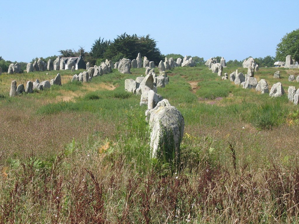
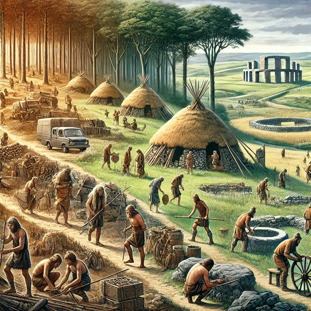
The 30–40 Ka Löwenmensch (lion-man) of Hohlenstein-Stadel and the “Sorcerer” engraving in Les Trois Frères cave mix human limbs with the heads or pelts of apex predators. Because predators belong squarely in the untamed realm, a figure that fuses with them signals an ability to cross the boundary between human order and wild chaos. Many pre-industrial shamans do exactly that in trance, “borrowing” animal bodies to hunt or fight on behalf of the clan, so archaeologists read these statuettes as early visual shorthand for a boundary-breaking, protector-hunter—the seed of the later hero idea.
Neolithic master-figures
At Göbekli Tepe (11 ka) the T-pillars show stylised human torsos wearing belts and loin-cloths, flanked by carved scorpions, lions and snakes. The animals cling to, but do not threaten, the pillar-men—suggesting the human counts as their master. Similarly, wall reliefs at Çatalhöyük (Turkey, 9 ka) show a reclining human grasping leopards by the tails. In both cases the message is “the hero-ancestor tames the dangerous world,” turning the Palaeolithic hunter’s one-off feat into a permanent, protective presence at the core of a settled farming community.
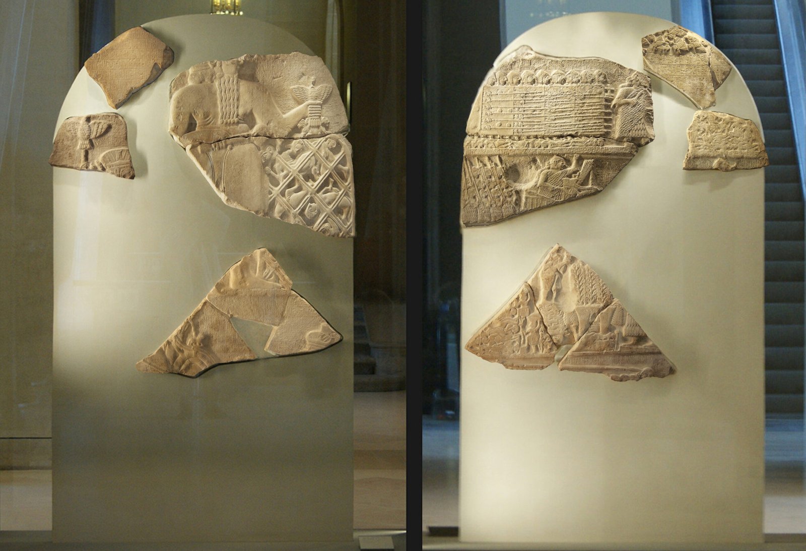
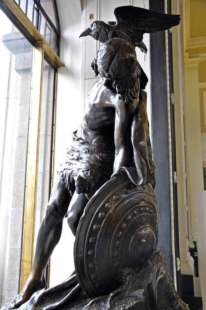
Stele of the Vultures in the Louvre Museum (enhanced composite)
Bronze-Age hero-kings
By c. 3000 BC we meet named rulers whose real political power is retold in mythic terms. The Narmer Palette shows the Egyptian king smiting a captive under a sky-falcon—his victory becomes cosmic order. The Stele of the Vultures (Lagash, Mesopotamia) has King Eannatum marching beneath Ningirsu’s battle-net, merging man and war-god. Most vividly, the Epic of Gilgamesh casts an actual Sumerian king as two-thirds divine, slaying monsters, digging wells and setting city walls: the first full literary hero-king, mapping civic achievements onto an archetypal champion narrative.
Iron-Age codification
From roughly 1000-300 BC literate cultures lock the roaming hero motif into fixed narrative cycles:
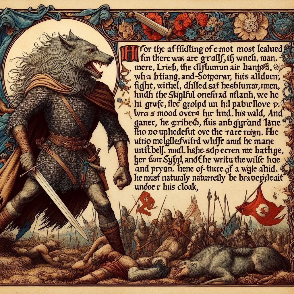
Achilles (Greek): divine mother, refusal-exile, duel with Hector, fatal heel—a template for proud, semi-divine warrior doomed by hubris.
Cúchulainn (Irish): unknown youth, single-combat tests, warp-spasm powers, tragic death defending Ulster, localising the pattern on Atlantic fringe.
Arjuna (Indian): divine paternity, crisis of duty, quest for celestial weapons, flaw of hesitation, eventual enlightened victory—Bhagavad Gita embeds the hero within dharma.
These Iron-Age epics lay down the hero’s journey “beats”- a prophecy of greatness, withdrawal, super-weapon, monster or duel, fallibility, costly triumph—that later stories from Beowulf to comic-book sagas still echo.
Where did the archetype originate?
A single birthplace is unlikely to be found; cognitive science suggests three converging pressures created it wherever Homo sapiens lived:
Coalitional warfare: groups that rallied round a conspicuously brave individual survived inter-band conflict better.
Costly signalling: a hero who risked death proved value and earned mates and status; myths preserve and teach that template.
Story compression: oral cultures package moral and survival lessons into memorable “once-for-all” figures – the hero is the easiest to remember.
Thus similar hero shapes appear to emerge independently: the Lion-Man carver, the Göbekli sculptor and the Narmer court artist lived millennia apart yet answered the same narrative need. After 3000 BC the iconography explodes: Mesopotamian cylinder seals of Gilgamesh, Egyptian smiting kings, Indus bull-slayer seals, Aegean boar-hunt frescoes—each culture remixing the same primal schema.
The hero archetype is then seen to be “echoed everywhere”, an it seems to it solve a universal social problem: who leads, who guards, and how risk is rewarded. Its symbolic DNA is visible from the Ice-Age Lion-Man, through Neolithic sanctuaries, into Bronze-Age royal art and all later myth cycles. Rather than one birthplace, we see recurrent invention – each time society scaled up or faced new threats, artists reached for the familiar silhouette of a powerful human standing between the group and chaos.
Could the hero archetype have began with the “best forager in the most dangerous patch”?
Anthropologists and evolutionary psychologists think that it may well be that the concept of the hero, may have emerged from hunter gatherers, honouring their best and bravest gatherers. And that this may lie at the root of heroic story-telling. The idea is built from three well-studied observations:
| Ecological fact |
Behavioural response |
Story outcome |
| Rich food patches (large game, honey cliffs, shellfish reefs in rough surf) often offer the highest caloric payoff but carry the greatest risk/injury, predators, falls. |
A minority of individuals repeatedly take those risks, sometimes returning with big hauls and sometimes dying. |
The band recounts those forays as cautionary but inspiring tales; over time the successful specialist is remembered as “the one who went where no one else dared” → proto-hero. |
How risk-heavy hunting turns men into living (and post-mortem) heroes
Ethnographers have tracked the mechanism in three foraging societies that still practise high-risk “big packages” hunting.
| Society & habitat |
Typical “big, risky” prey |
Why it is risky / hard |
Immediate social payoff |
Long-term reputational payoff |
| Hadza (savanna woodland of northern Tanzania) |
Giraffe, kudu, buffalo, zebra |
Requires stamina tracking, close bow-shot, real danger of gore-injury; success rates < 3 % per attempt. |
Entire camp (30–50 people) fed for two days; hunter gets A but no larger share. |
Hawkes, O’Connell & Blurton-Jones (1991–2001) show hunters who land ≥ 1 large carcass per month are named far more often as desirable camp-mates and marry younger, polygynously. |
| Ache (sub-tropical forest, eastern Paraguay) |
White-lipped peccary, tapir |
Peccaries travel in aggressive herds; tapirs flee into dense cover; hunters go solo with bow, may suffer fatal wounds. |
Meat shared by strict rule; hunter’s family portion identical to others. |
Hill & Kaplan (1987–1990) found widows of “elite big-game hunters” remarried fastest; songs retell their feats for decades, citing exact kill counts; a post-mortem hero cult. |
| Meriam (coral-reef and islet environment, Torres Strait, Australia) |
Green turtle, dugong (sea cow) |
Deep-water harpooning from small canoe; storms, shark risk; capture rate < 0.2 per hunter-day. |
Entire island community eats; hunter directs distribution, creating political alliances. |
Bliege Bird & Smith (2005) show successful dugong hunters are 10 × more likely to hold council leadership; after death they are spoken of as zugubal (ancestral spirit-heroes) who “still ride the turtle tracks in the sky.” |
What the three cases teach us
Prestige not provisioning: Although meat is evenly distributed, status, mates and political sway flow disproportionately to the risk-taking hunter.
Memory selects for drama: The Hadza recount giraffe kills in informal “epic” evenings; Ache elders compose formal songs; Meriam print the hunter’s spirit into star-lore. Mundane monkey or fish catches never get this treatment.
Risk–reward ratio drives mythic condensation: The rarer and deadlier the prey, the more the narrative sharpens: one or two high-stakes exploits eclipse dozens of safe successes, simplifying the persona into an archetypal template; skill, courage, generosity, sacrifice.
Hero after death: Each society honours fallen hunters: Hadza carve giraffe-hoof marks on grave posts, Ache sing jay-rera elegies listing biggest kills, Meriam give special star-names. Ancestral hero status persists long after physical provisioning ends.
Relevance to the hero archetype
These real-world patterns fit both Jung’s and Campbell’s theoretical proposals:
- Call & venture: The hunter leaves safe camp, entering lion grounds or dangerous fishing waters.
- Ordeal: The possibility of gore, storm, or spirit attack.
-
Boast & gift: The carcass is displayed, the amount and quality of the catch praised, blessed and redistributed.
-
Apotheosis: Stories, songs and imagery elevate hunter into model of bravery and sharing, the stories and effigies carry their name and deeds into the future, beyond their death.
Across continents, the concrete economics of meat and danger furnish the raw material for the same myth-making machinery that later produces Lugh, Arthur, or St Michael—only scaled up from the campfire to the national epic.
From forager tales to mythic “perfect hunter”
Small-scale societies frequently develop a culture-hero who first mastered a perilous resource:
| Culture |
Culture-hero |
Dangerous bounty |
| Inuit (Central Arctic) |
Nuliajuk tamer of sea beasts |
Deep-ice seal hunting in dangerous leads |
| San (Kalahari) |
!Kung’s Haasi |
Honeybee cliffs with lethal falls & stings |
| Northwest Coast |
Raven |
Salmon trapped at perilous tidal falls |
These figures encode technical knowledge (how to approach the cliff / harpoon the seal) and provide a moral template: courage plus generosity of sharing.
How real hunting feats grow into “perfect-hunter” myths
Small-scale societies frequently develop a culture-hero who first mastered a perilous resource:
| Culture-area |
Mythic culture-hero |
The perilous resource |
Key episodes that transmit know-how |
Moral lesson carried in the tale |
| Inuit (Central & Eastern Arctic) |
Nuliajuk / Sedna (sometimes male hunter, more often sea-mother goddess) |
Ringed-seal and walrus taken at moving pack-ice leads, where one slip means drowning |
1 She is thrown into the sea; as she clings to the kayak gunwale, her fingers are cut and turn into seals and whales.
2 Hunters must dive to comb her hair and soothe her anger, or the ice will not open.
|
The seal harvest is conditional on ritualised courage and respect; success depends on cooperating with the sea-mother, not brute force. This speaks of flow and balance in their relationship with nature: The hunter in tune with the mother of life. |
| Hoan & Naro San (Kalahari Desert) |
!Kung’s Haasi (literally “Honey-guide Bird transformed”) |
Wild-bee honey in sheer cliff hives with swarming stings |
1 Haasi follows the Indicator bird, chants the right song to keep bees calm.
2 He smears wax on hands, uses a forked branch as a ladder, invites the camp only after first taste.
|
This shows a deep relationship with nature, involving trust, skill, and a ritualised behaviour that ensures a safe harvest in a perilous situation. The bird being natures messenger. Showing which honey the tribe can take, and which, they therefore, cannot.
|
| North-West Coast Salish & Tlingit |
Raven (trickster-hero) |
Sockeye salmon trapped at dangerous tidal narrows |
1 The Raven steals the river-owner’s weir or dam, smashes it so the fish escape upriver.
2 He understands, and teaches the people the first-salmon ceremony to ensure the run returns yearly.
|
Clever risk unlocks staple food, but community must reciprocate with ritual thanks or the salmon will withhold themselves next season. |
What “mastering the peril” really means
Technical blueprint
Nuliajuk stories embed knowledge of ice-edge reading and propitiation rituals; every unveiling of a lead recapitulates the myth.
Haasi tales encode mozzie-smoke, wax handling, and safe descent after harvest.
The Raven cycle teaches tide-timing, weir technology, and the taboo against catching the last fish.
Risk rationale
The hero’s unique bravery validates why ordinary members shouldn’t attempt the feat alone. It limits fatal copycat acts while still encouraging collective support.
Generosity norm
After the kill or acquisition the hero shares—the myth equates hoarding with supernatural punishment (Raven is punished for greed in some variants).
Spiritual contract
Each myth frames the resource as personified (Sea Mother, Bee Spirits, Salmon People). Human access is never free; ritual “grooming,” song, or first-fruit offerings renew the pact that the hero forged.
From local hero to universal archetype
These forager myths contain the same structural flows are then later expanded and into the Iron-Age hero epics:
| Beat in small-scale myth |
Macro-hero version (e.g., Lugh, Hercules) |
| Risky quest for crucial food |
Quest for life-saving cattle of Geryon or Pigs of Tir na nÓg |
| Spirit / monster tests bravery |
Balor’s evil eye, Hydra’s poison heads |
| Success achieved by brains + nerve |
Lugh’s spear precision; Hercules uses lion skin as shield |
| Mandatory sharing or thanksgiving |
Lugh institutes Lughnasadh; Hercules dedicates spoils to gods |
Expansion to war-hero
Once Sedentism and inter-group conflict intensified (from the Neolithic period onwards), the same narrative logic shifted from hunting risk to combat risk. Success in battle is likewise rare, high-payoff, dangerous—easy to package as heroic myth. The hunter-hero template was simply redeployed:
Spear vs mammoth → spear vs invader
Navigating dangerous waters → navigating enemy lines
Thus Heroes that form heroic archetypical legacies such as Lugh, Arthur and later Michael inherit a structure first honed in dangerous-patch foraging: a specialist confronts what others avoid, wins resources/order, returns as benefactor.
Ancestral embodiment
Lineages often claim descent from the specialist— “our clan mastered the falls.” Archaeologists find:
Trophy display (lion teeth, boar tusks) buried with particular males.
Totemic emblems linking a kin-group to the prized animal or patch.
Those graves become pilgrimage nodes; the remembered hunter merges into an idealised ancestral guardian – the nascent hero-ancestor.
The daily tasks of Palaeolithic foraging where few dare, but many benefit, may well have created both the selective pressure and the social appetite for celebrating a “perfect hunter.” That celebration probably crystallised into myths, myths often enhanced through a deep relationship with both nature, and increasingly well defined spiritual connection, and explanation.
As new dangers (warfare, monsters, cosmic dragons) emerged, the underlying heroic shell stayed intact while the external foe changes. The hero archetype can therefore be seen almost certainly to have grown out of stories of the handful of individuals willing to enter the most hazardous food patches and live to share the spoils, and later societies mapped the same narrative onto every new realm of risk that mattered.
Stage in the “life-cycle” of a hero myth
| Stage in the “life-cycle” of a hero myth |
What usually happens in most traditions |
Why the pattern keeps repeating |
| Local point of origin |
A real (or plausibly real) problem-solver takes exceptional risks: the hunter who braves the hyena den, the voyager who crosses open sea, the warrior who wins a first skirmish. |
Small groups remember rare, high-pay-off behaviour — it helps them imitate success and assign status. |
| First narrative crystallisation |
The deed becomes an episode told around the fire; over just a few retellings the human gains helpful spirit-allies or luck-omens. |
Storytellers compress detail, heighten drama; adding a hint of the supernatural marks the event as morally instructive, not mere gossip. |
| Expansion into a cycle |
New “wins” solidify the myth: the hero invents tools, founds a lineage, defeats a monster that threatens the whole group. Each answers a practical question (“Where did we get spears?” “Why do we dance before hunting?”). |
Once a figure is recognised, new social or ecological challenges can be attached as “prequels” or “sequels,” saving inventors the labour of coining a fresh protagonist every time. |
| Integration into a pantheon |
The character is lifted above genealogy — now a demi-god, culture-hero or full deity. Worship (or ritual respect) develops at places linked to the original exploit. |
Converting the champion into a god secures group identity: the hero’s feats become timeless guarantees of territory, law or cosmological order. |
| Subordination to a still higher power |
In strongly theistic systems the former hero shifts one more rung down: from god to arch-angel / saint / “first king” who acts for the supreme deity. |
Monotheistic or imperial religions absorb local stories but must keep ultimate sovereignty clear; demoting the old hero maintains continuity while asserting new orthodoxy. |
Why the similarities?
Convergent social ecology
Wherever humans live in bands or tribes, they depend on someone’s willingness to tackle risky-but-rewarding tasks. The social payoff (food, defence) and the signalling payoff (prestige, mates) are identical whether the quarry is seal, boar, jade, or an enemy war-party.
Cognitive compression
Human memory prefers a single, exaggerated protagonist to a list of ordinary contributors. So separate admirable deeds tend to coalesce onto one “perfect” figure.
Narrative problem-solving
Myths are cultural troubleshooting manuals. If a community already has a celebrated name, sewing new lessons onto the old hero is quicker than inventing a fresh personality.
Theologisation as politics
As groups merge into chiefdoms or states, leaders gain by folding each tribe’s champion into a shared divine roster: “Your Bear-Killer is really my Thunder-God’s brave nephew.” Over time the original person disappears behind the collective edifice.
Concrete examples
| Initial “specialist” |
Later pantheon slot |
Structural echo elsewhere |
| Polynesian navigator Māui (fishes up islands, snags the sun) |
Demigod, trickster-culture hero |
Trickster-innovator pairings of Raven (NW Coast) and Coyote (Great Basin) |
| Greek Herakles (strongman monster-killer) |
Becomes full Olympian; later demoted to saint-like protector in Byzantine folklore |
Hindu Bhima, Norse Thor share strength + monster duel cycle |
| Celtic smith-hero Goibniu / Govannon |
God of the forge under Tuatha Dé Danann |
Mesopotamian Kulla, Yoruba Ogun, each born from skilled artisan ancestors |
| Historical war-leader Arthur |
Medieval rex quondam, later Christ-like Grail king |
Mede-Persian Kay Khosrow, early Japanese Yamato Takeru mirror arc from secular prince to semi-divine saviour |
Independent tribes create their own heroic forebears, but because the social functions of risk-taking, teaching, and identity-marking are everywhere the same, those heroes evolve through remarkably similar thematic stages, eventually shedding much of their human detail and settling into a symbolic niche within a larger divine or semi-divine hierarchy.
That is why a Bronze-Age smith, a Romanised war-lord and a Hebrew arch-angel can look like variants of one indestructible template: each is the latest mask worn by a role that human groups have needed — and mythologised — since the first hunter walked beyond the safe horizon in search of better food.
Lugh’s “claim” as hero
There are a number of reasons to consider Lugh as embodying that heroic template:
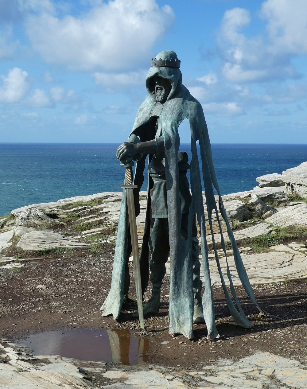
The single decisive deed – at the Second Battle of Mag Tuired he kills his grandfather Balor, whose evil eye could wither armies. This is the classic “hero slays the chaos-monster/tyrant” scene, comparable to Perseus vs Medusa or Michael vs the Dragon.
Extraordinary birth and destiny – his mother is Eithne, Balor’s daughter, and prophecy foretold that Balor would be killed by his grandson. The threatened infant who grows up to fulfil the prophecy is a standard hero motif.
Exile and return – he is raised away from his birth-tribe (fostered by Manannán or Tailtiu), returns at maturity, and proves his worth at the gates of Tara by demonstrating mastery in every craft. The “outsider returns as saviour” is central to the hero’s journey.
The perfect warrior – he wields the Spear of Assal, a weapon of unstoppable victory. Weapons with inherent, almost divine power (Excalibur, Achilles’ shield, St Michael’s flaming sword) are hero emblems par excellence.
Where Lugh goes beyond a “mere hero”
Polymath identity: Unlike many one-note heroes, Lugh is called Samildánach (“possessor of many skills”). He embodies not just physical bravery but craftsmanship, artistry, rulership, judgment, and inspiration.
Integration into the divine order: The Tuatha Dé Danann accept him not as a passing champion but as a sovereign figure. He becomes king after Nuada’s death. This places him at the top of the pantheon — the slot usually reserved for a sky- or thunder-god.
Festival and cult: The great harvest festival Lughnasadh (“assembly of Lugh”) is instituted in his honour, rooted in rites of sovereignty and agriculture. This ritual enshrines him not just as warrior but as guarantor of the fertility of the land — something most “hero” figures never achieve.
A Comparison with other Irish pantheon figures
| Deity |
Role |
Relation to Lugh’s “hero” claim |
| Nuada |
King of the Tuatha, “silver hand” after maiming |
A tragic hero-king: his wound disqualifies him from sovereignty. Lugh surpasses him by being whole and perfect. |
| Dagda |
“Good god,” fertility and magic |
More fatherly, earth‑bound; not a hero in the martial sense. Lugh is younger, radiant, sharper. |
| Ogma |
Champion, eloquent warrior |
Closer to a heroic strongman (like Hercules); lacks Lugh’s all-round genius. |
| Cúchulainn |
Semi-divine mortal hero |
In many ways Cúchulainn is Lugh’s mortal double: a battlefield prodigy who dies young. Unlike Lugh, he never crosses into sovereignty or divinity. |
It can therefore be seen that Lugh is very much a hero archetype, and may well be one part of a common shared archetypical lineage which may be “baked-in” to human DNA. He fits the pattern of miraculous birth, exile, return, single decisive victory, possession of a unique weapon. But he is also a culture-hero and sovereign god, elevated above the normal champion’s slot. His “claim” is therefore stronger than any single Irish hero: he monopolises nearly every heroic quality and then ascends to rulership, where others (Nuada, Cúchulainn) falter.
In archetypal terms, if Cúchulainn is the “young hero,” Lugh is the “perfected hero”: The point where the archetype fuses into divinity and becomes a lasting cornerstone of the pantheon.
Can all of these heroes, myth and real, carry the same “DNA”?
Let us face facts: There are no facts! What we can do, is take a diverse sample, and compare the key aspects of their mythology, and just look for similarities and commonalities.
| Element of the statement |
What holds up |
Where it over-compresses |
Evidence / counter-evidence |
| All three are ‘hero’ figures |
Each leads a decisive battle against a monstrous or chaotic foe:
- Lugh slays Balor at Mag Tuired
- Arthur defeats giants, Saxons and sometimes dragons
- Michael casts down the Dragon (Revelation 12)
|
“Hero” is a very broad Jungian/Campbellian archetype: most warrior-leaders fit it, so similarity on this level doesn’t prove lineage. |
Comparative myth analyses (Dumézil, Campbell) put them all in the “warrior champion” slot, but cluster dozens of other figures there too. |
| Linear refinement from Celtic god ➜ legendary king ➜ Christian archangel |
Christian authors often grafted familiar pagan motifs onto saints and angels; St Michael cult sites in the Isles do sit on earlier high-place shrines. |
No textual or etymological chain links Lugh ⇢ Arthur ⇢ Michael.
Arthur’s name is Latin Artorius not cognate with Lugus.
Michael is Hebrew Mî ḵā’ēl (“Who is like God?”). |
Arthurian tales borrow Celtic mythic units (Otherworldly sword, sovereignty goddess) but also draw on late-Roman military lore. Michael’s cult arrived with Mediterranean Christianity, not via British Celtic tradition. |
| Weapons as archetypal constants (spear ▸ sword ▸ flaming sword) |
Lugh’s spear, Arthur’s Excalibur, Michael’s sword all symbolise divine or royal authority and victory over chaos. |
Weapons are common hero attributes; the shift from spear to sword reflects changing military tech rather than evolving archetype alone. |
Spears dominate Bronze–Early Iron Age hero myths (Lugh); swords dominate post-Roman literature (Arthur) and angelic iconography (Michael) because those were the prestige arms of each milieu. |
| ‘Hero of God’ framing shows Christian refinement |
Michael’s iconography recasts martial heroism in a fully monotheistic frame: the warrior fights for God, not as a semi-divine king. |
Arthur’s later‐medieval “rex quondam” becomes Christ-like, but in earliest Welsh sources he is worldly. Lugh is explicitly divine himself, not God’s deputy. |
Shift from immanent warrior-god ➜ mortal champion ➜ celestial general mirrors Britain’s conversion-era ideology, but is not a straight lineage—more a set of re-mapped functions. |
We can also compare and contrast as follows:
Shared slot in the Indo-European “warrior champion” repertoire
All three answer the narrative need for a culture-guardian who overcomes an existential monster or invader.
That similarity is typological, not necessarily genealogical.
Cultural resets override direct descent
Lugh belongs to the polytheistic Iron-Age Gaelic cosmos.
Arthur begins as a possibly historical war-band leader whose legend absorbs Celtic mythic motifs.
St Michael arrives from the eastern Mediterranean with Christianity; any overlap comes from Christian writers overlaying older heroic themes onto a biblical agent.
Refinement vs. repurposing
Each figure is refined to suit the moral and theological ideals of its age—but each also drops earlier traits (Lugh’s craftsman/solar aspects vanish in Arthur; Michael loses kingship, marriage, earthly community).
Influence pathways
There is good evidence for Christian re-use of high-place sanctuaries once devoted to pagan deities (several “St Michael’s Mounts” stand where sun-god or sky-god worship is suspected), but no medieval text equates Michael with Lugh or Arthur.
Arthurian romances later Christianise Arthur (e.g., Quest for the Grail), but that is a convergence, not an inheritance from Michael.
How the single “perfected hero” idea travels, splits and re-merges
Taking a wider look at the post Iron-Age hero cults, and how they overlap each other:
| Region & figure |
Core heroic episode |
Extra layers added by local culture |
Where it overlaps Lugh’s pattern |
Where it diverges |
| Ireland – Lugh |
Kills Balor at Mag Tuired; wins every craft at Tara |
Festival of Lughnasadh secures harvest; rises to kingship of Tuatha Dé Danann |
Miraculous birth, exile-and-return, unstoppable weapon, becomes guarantor of land |
Retains full divinity, not just champion |
| Britain – Arthur |
Defeats Saxons, giants; wins magic sword; leads Round Table |
Medieval romance makes him rex quondam, then Grail-seeker; death on Avalon, messianic return |
Hidden upbringing, magical weapon, single decisive victory |
Remains mortal king; tragedy & return motif dominate instead of permanent sovereignty |
| Heaven – St Michael |
Casts down the Dragon; weighs souls |
Christian angelology turns him into Heaven’s field-marshal; psychopomp, healer |
Monster-slayer, weapon with divine authority, protector of community |
Pure servant of God, not a sovereign; no birth/exile narrative |
| Iberia (Galicia) – Santiago Matamoros |
Appears at Clavijo (legend), routing Moors with flashing sword |
Localised as patrón de España; linked to pilgrimage road to Compostela |
Mounted warrior delivers victory at crisis; cult-festival parallel to Lughnasadh |
Entirely Christian saint; heroic epiphany not life-story; martial horse motif |
| Gaul / Celtic mainland – Lugus/Mercury |
No narrative survives; Romans identified Lugus with Mercury, patron of boundaries & trade |
Triadic statues (Mercury with Rosmerta) show craft & communication aspect |
Shares etymology and multi-skill epithet ‘inventor of all the arts’ |
Loses combat episode; becomes civilizing god not battlefield hero |
| Germanic North – Thor |
Slays giants (Jörmungandr, Hrungnir); protects Midgard |
Hammer returns to hand, oath-ring hallowing; Thursday named for him |
Monster combat, magical returning weapon, protector of humanity’s realm |
More thunder-god than ruler; never becomes culture-hero or king |
| Slavic East – Perun / St Ilija |
Hurls lightning at snake-dragon Veles |
Christian layer equates Perun with Elijah; icons show fiery chariot |
Sky-bolt weapons, guardian of cosmic order vs serpent chaos |
No exile/return, no multi-skill craft dimension |
| Greek – Herakles |
Twelve labours cleanse monsters & thieves; apotheosis on Olympus |
Model for later hero-cults; clubs & lion-skin as triumph tokens |
Superhuman feats, killing chaos beasts, ends as god |
Lacks political kingship, but becomes pattern for mortal “strong-man” heroes |
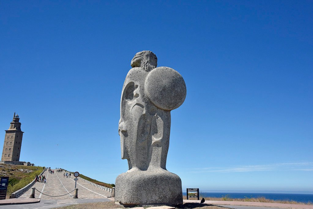
| Galicia (Celtic folklore) – Breogán & his sons |
Found mythical Brigantia, sight Ireland from tower |
Origin legend of Irish Gaels; tower in A Coruña is Galician identity marker |
Culture-founder, voyage over perilous sea; sacred geography |
Non-combatant hero; emphasis on exploration/colonisation over monster-slaying |
Patterns that repeat from Lugh outward
Monster-slayer + community saviour – Whether the dragon (Michael), Balor (Lugh) or Saxons (Arthur), a super-enemy defines the hero.
Weapon of authority – Spear of Assal, Excalibur, flaming sword, hammer Mjölnir, lightning-bolt; the armament itself becomes cult object or relic.
Festival or pilgrimage – Lughnasadh games, Santiago’s 25 July feast, Thor’s Thursday rites, Michaelmas: the people re-enact protection and harvest security.
Elevation or translation – Hero ends as king, god, angel or celestial patron (Arthur’s Avalon sleep; Herakles on Olympus; Michael enthroned as archangel).
The variables
- Degree of divinity:
- Lugh / Thor / Perun start as gods.
- Arthur / Breogán are mythicised mortals.
- Michael / Santiago are imported biblical or hagiographic figures overlaid on older hero ground.
- Dominant function:
- Ireland & Wales favour polymath-craft + kingship (Lugh, Arthur).
- Continental thunder-gods focus on weather-warfare.
- Santiago, Michael stress military epiphany within Christian cosmology.
- Galician Breogán shifts to voyager-founder, echoing a coastal trading lens.
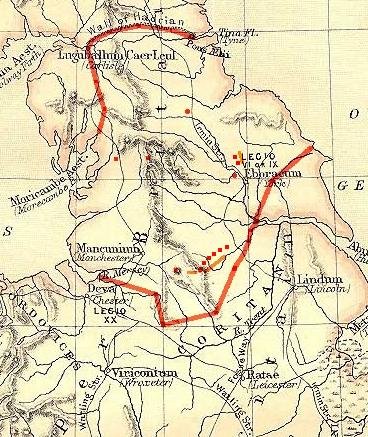
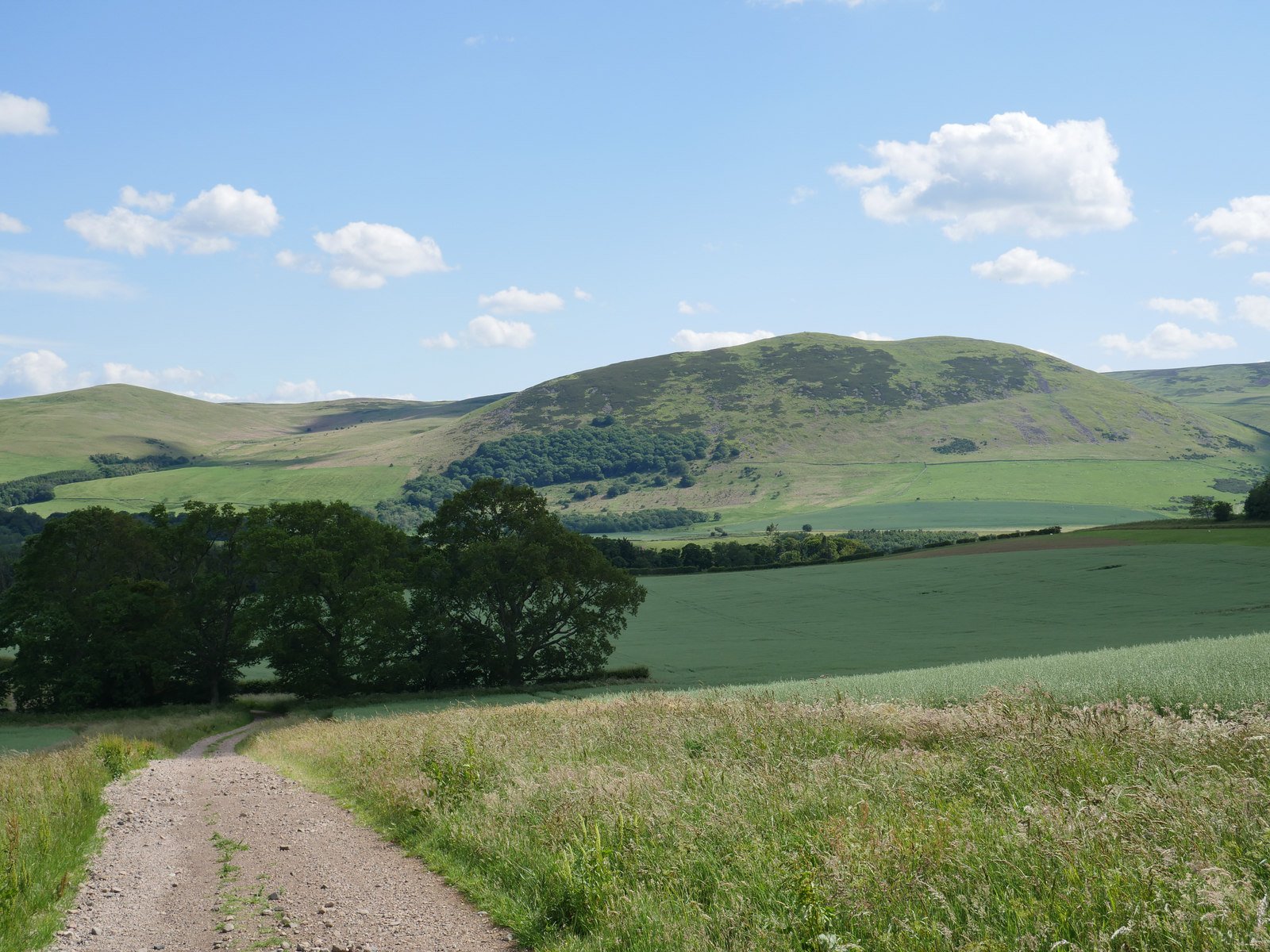
Why Galicia may be a key zone
- Toponyms such as Lugo (Lucus Augusti) and Lugones keep Lugh/Lugus visible.
- Roman Mercury-Lugus cult melds with later St Michael hill-shrines (Monte Medulio, San Miguel de Breamo) and finally with Santiago-Matamoros as the mounted protector of Christendom provide interesting cross-connects.
- Thus Galicia shows layer-cake accretion: Celtic Lugus ⇒ Roman Mercury ⇒ Michaelite hill chapels ⇒ Santiago knight-hero. Each layer keeps the “champion-guardian” role but swaps theology and iconography.
What the comparison tells us
The hero archetype acts like an empty sleeve – local cultures can insert their key concerns (craft, kingship, thunder, crusade, voyage) into an inherited storyline of risk, victory, and social renewal.
Lugh sits at the “maximal” end – he fuses skills, rulership, warfare and divine status; later figures usually keep only two or three elements.
Christianisation does not erase the pattern – it merely channels the champion into service of the one God, producing Michael and Santiago.
Peripheral regions (Galicia, Brittany, Scotland) preserve hybrid forms because successive waves (Celtic, Roman, Christian) pile up without necessarily a total overwrite.
So Lugh is indeed a hero archetype—and by tracking the same structural features outward to Arthur, Michael, Santiago and beyond, we see how Europe continually re-clothes a very old narrative chassis in new theological and political fabrics, while the underlying role of “great protector who turns chaos into order” stays recognisably the same.
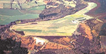
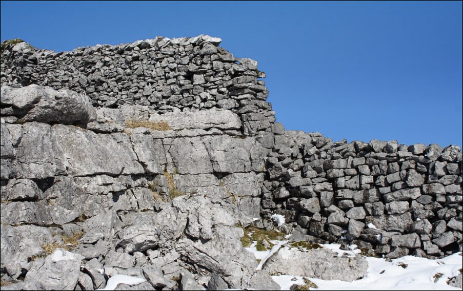
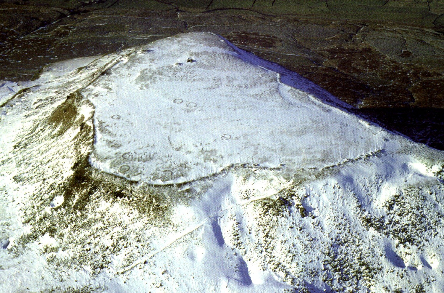
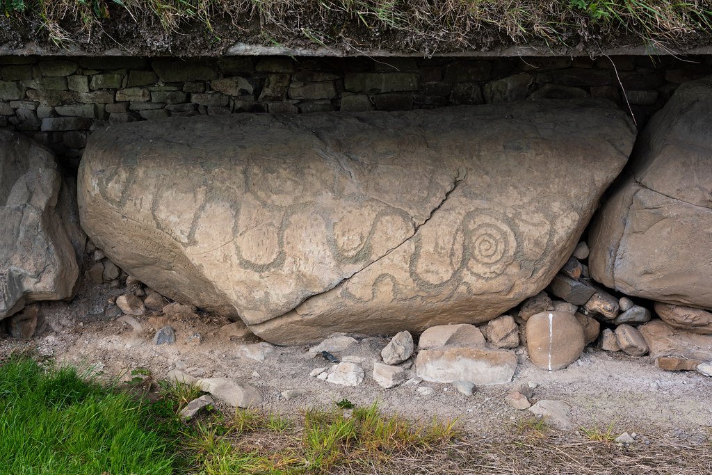
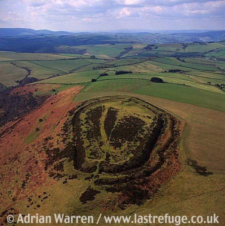
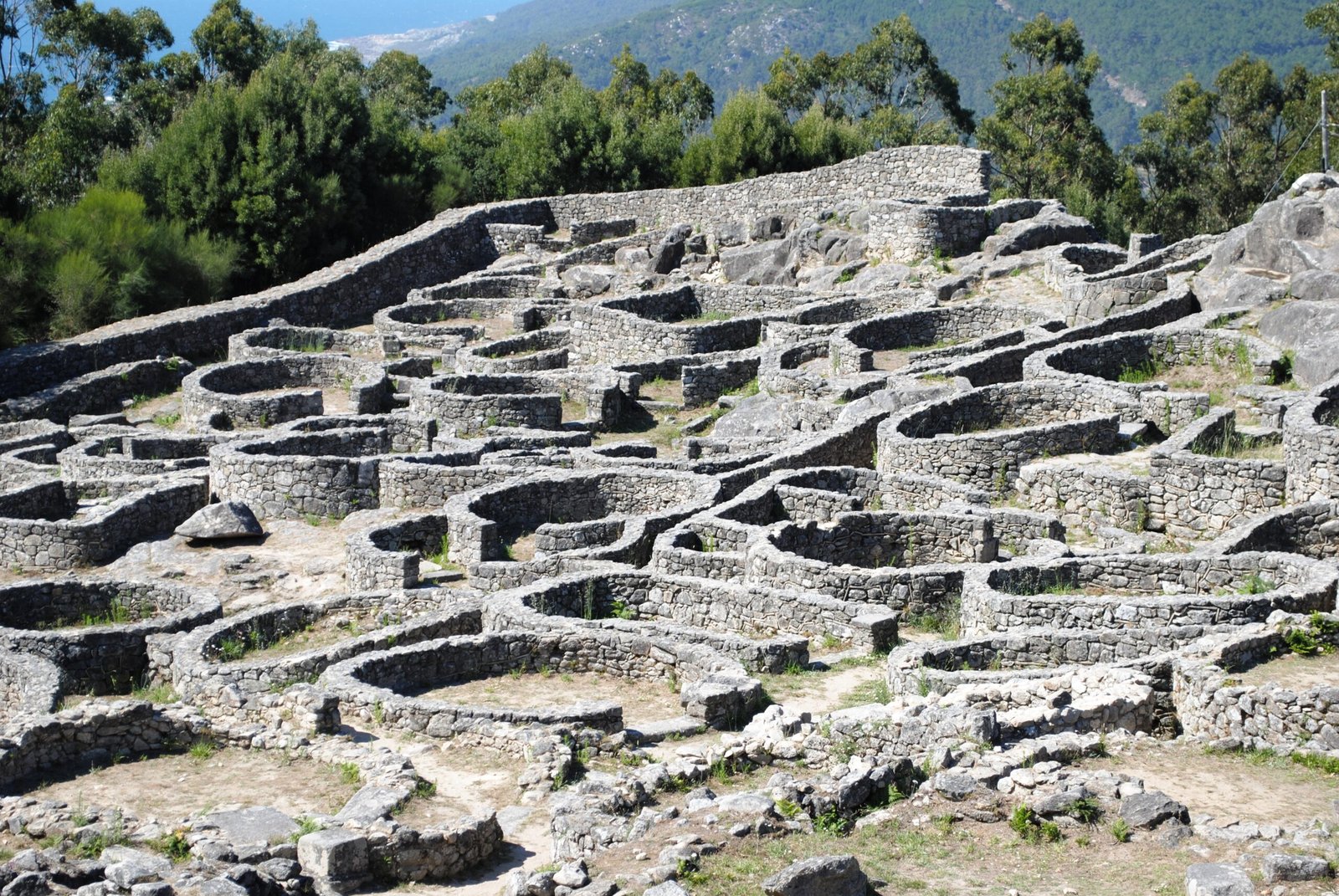
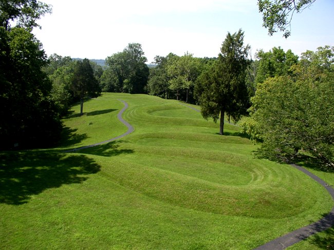
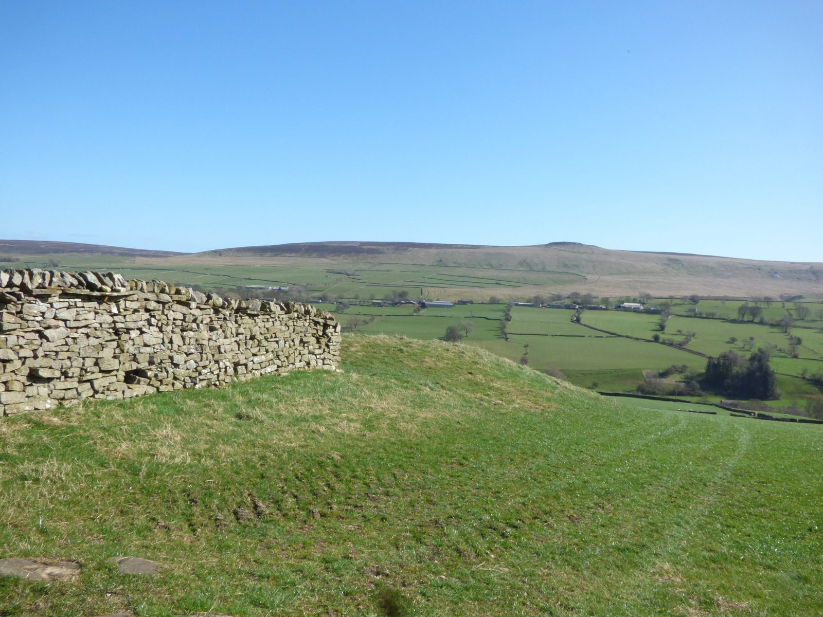
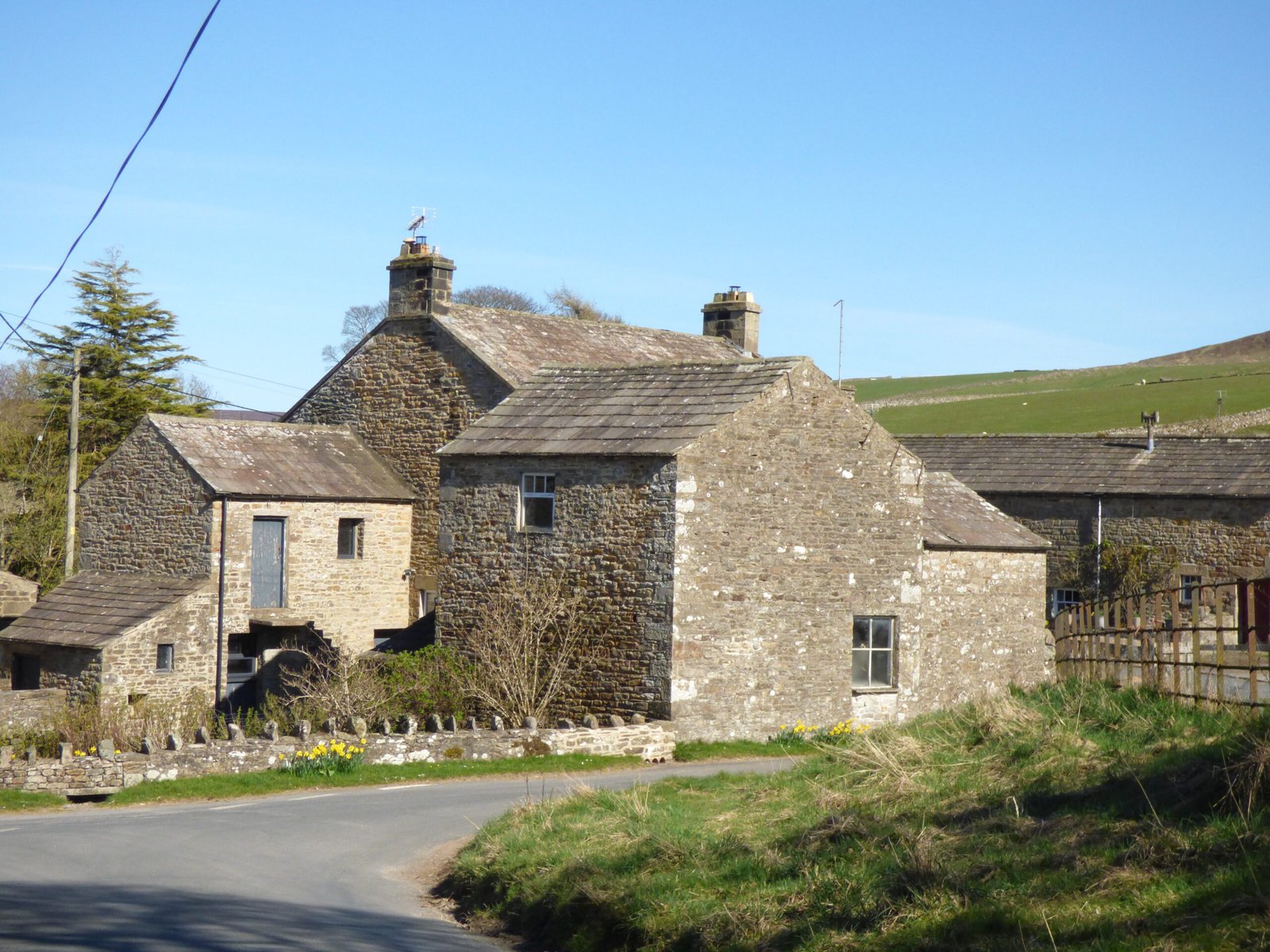
The Christian chapels on Galician castros – conquest or co-existence?
Many Iron Age castros in Galicia also form Christian shrines and places of pilgrimage. Is this a complete rewrite of the nature of those sites in a Christian frame? Or have the older, Iron-Age and Roman tradition’s also been “folded-in” to those newer, Christian practices? Archaeologists, historians of religion and folklorists now agree tend to agree on one broad answer: both suggestions are partly true. The medieval Church did plant crosses, hermitages and pilgrimage routes on the summits of Iron-Age hillforts (castros) as an assertion of Christian authority, but it did so because the places were already felt to be numinous and particularly spiritual by local communities. The new cults therefore absorbed rather than erased the older sense of sacredness.
What the record shows
| Evidence |
“Triumph over paganism” reading |
“Syncretic adoption” reading |
| Stone chapels inside forts, e.g. Capela de Santa Trega on Monte Santa Trega; San Xiao at Castro de Troña |
Building a church on the acropolis proclaims Christ’s victory over demons linked to the old gods. |
Clerics chose the spot because people already climbed it for seasonal rites; replacing the shrine guaranteed the flock would keep coming. The chapel to Santa Trega still hosts an annual penitential climb that echoes earlier hill-top offerings. (turismoaguarda.es) |
| Pilgrimage and romarías held on castro summits |
Processions, Mass and viacrucis overwrite pagan gatherings. |
The calendar often aligns with pre-Christian dates (early August on Santa Trega ≈ Celtic Lughnasadh); saints’ legends borrow motifs of storm-control and healing long tied to hill spirits. |
| Iconography on site (crosses, cruceiros) facing seaward or skyward |
Marks of a reclaimed landscape; the cross nullifies “pagan demons”. |
Placement matches prehistoric sight-lines (sunrise alignments, river mouths); Christian symbol piggybacks on the same cosmological axis. |
| Toponymic continuitye.g. Lugo < Lucus Augusti < Lugus |
Latin/Christian names overwrite Celtic theonym. |
The survival of the root Lug- hints that the old deity’s memory lingered beneath the Roman and Christian layers. |
How scholars explain the dual dynamic
Mission strategy: Early medieval bishops everywhere in Western Europe reused pagan high-places because they were natural assembly points; Gregory the Great’s advice to “turn the idol temples into churches” (letter to Mellitus, AD 601) set the tone.
Social leverage: For rural Galicians the hilltop was communal property, used for grazing and sanctuary; installing a saint ensured the Church sat at the centre of village economics and identity without costly land purchases.
Continuity of function: Castros already served as liminal landmarks between farm and wild, sea and land. Christianity offered a new guardian (saint, archangel, Virgin) but kept the protective and intercessory role once attributed to hill-spirits or sky-gods.
| Criterion |
Assessment |
| Do chapels symbolise Christian victory? |
Yes. Sermons and hagiography often portray the saint “banishing devils” from the hill. |
| Did local belief in the hill’s power persist? |
Also yes. Pilgrims still ascribe healing, fertility or weather-luck to the site in terms that echo earlier folklore. |
| Did the Church tolerate residual folk rites? |
Usually, provided they were re-framed as penance or Marian/saintly devotion; outright “pagan” elements were pushed to the margins but not always stamped out. |
| Net result |
Syncretic Christianisation: a negotiated layering, not a clean sweep. |
Modern ethno-archaeological studies of the of Santa Trega, Troña and other castros stress that villagers never spoke of “destroyed” pagan gods; instead they say the saint or archangel “took the old power under his wing.” That language betrays a perceived continuity under new management.
We can therefore suggest that the Christian iconography on Galician hillforts is both a sign of ecclesiastical appropriation and evidence that the Church folded enduring local sacrality into its own system. The stones, views and ancient ramparts kept their aura; the Cross and the chapel simply re-named the resident protector. In practice the line between “defeat” and “acceptance” is blurred—the old gods were not so much exiled as baptized under new patronage.
Ireland shows a similar two-layer picture—confrontation and absorption
If we now return to Ireland, we can see a similar story evolved as Christianity took hold:
| Feature |
“Defeat of paganism” reading |
“Continuity under a new name” reading |
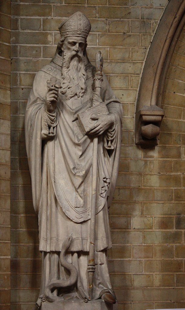
| St Patrick “drives the snakes from Ireland” (first attested 11th c.) |
Snakes stand for the pagan druids; Patrick’s victory is a polemic that Ireland is now wholly Christian. |
Ireland never had native snakes; the image is borrowed from Mediterranean hagiography. Early sermons gloss serpents’ as “demons of idolatry” rather than real animals—so it is a spiritual cleansing metaphor, not a memory of literal suppression. |
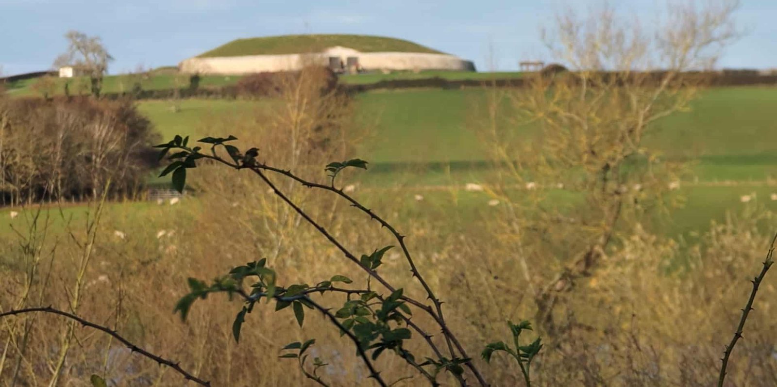
| Christian takeover of sacred hills – Croagh Patrick, Hill of Tara, Slane, Uisneach |
Founding monasteries on high places proclaims Christ’s dominion where sky-gods (e.g. Lugh on Uisneach) once reigned. |
Pilgrimage to Croagh Patrick in July (Reek Sunday) keeps the calendar slot of Lughnasadh; the climb, fasting and sunrise rituals replicate pre-Christian hill assemblies, now framed as penance and Mass. |
| Holy wells and sacred trees |
Ancient healing springs and oak groves are re-dedicated; pagan rites condemned as “superstitions.” |
Many wells are still called Tobar Bríde, Tobar Lugh, yet bear a saint’s statue. Offerings of rags or coins—attested in Celtic Iron Age—continue today with a rosary and a candle. |
| Saint–goddess mergers – Brigid of Kildare |
The abbess-saint replaces the fire-goddess Brigid, extinguishing her cult. |
Same shrine at Kildare keeps a perpetual flame; poems still call the saint “mother of poetry, smithcraft, healing”—the triad of the earlier goddess. Scholars see a straight syncretism, not erasure. |
How the “snake” motif works in Patrick’s legend
Biblical shorthand – In Christian scripture the snake is Ha-Nahash, the Satanic tempter. Medieval hagiographers routinely say that saints expelled snakes to signal victory over the Devil (e.g., Paul of Thebes in Egypt).
Polemic against druids – Irish clerical writers of the 7th–10th c. equate druidic wands and serpent symbolism with demonic arts. Saying “Patrick banished snakes” is shorthand for “he defeated druidic magic.”
Homiletic drama – Ireland’s real absence of snakes makes the miracle safe to claim; nobody could refute it. By the 12th c. the story is fixed in Vita Tripartita Sancti Patricii.
So snakes = “bad aspects” of the old religion, not its benevolent deities. Good qualities—healing wells, harvest fairs, fire symbolism—were baptised rather than banished.
Parallel with Galicia and other fringe zones
| Ireland |
Galicia |
| Hill of Uisneach (centre of Ireland) – Lughnasadh assembly ➜ St Patrick’s fire and later Marian pilgrimage |
Monte Santa Trega castro – Lugus/Lugh shrine ➜ Chapel of Santa Trega with August romaría |
| St Brigid merges with Brigid the goddess; perpetual flame survives |
St Brigantia lighthouse legend on A Coruña Tower preserves name of Brigantia, Celtic goddess |
| Holy wells retitled “Tobar Mhuire” (Our Lady’s Well) |
Rock-cut springs on castros now have crosses but keep coin/rag offerings |
Both regions show a Christian super-imposition chosen precisely because the older sanctity would draw the faithful.
Is there a hero in you?
So we have suggested that the hero may well be an archetypical trait that is inherent in our “DNA”. Does that mean that you might have it, yourself?
In Jungian terms, the answer is yes: the hero is not only a story out there but a potential in every persons psyche. Jung saw mythic figures as archetypes: Deep-lying, inherited patterns of behaviour and imagination that surface in dreams, art, religion and personal crisis. When you feel the impulse to break old limits, confront a fear, or rescue a threatened value, you are touching the hero archetype within your own unconscious.
Jung’s map of the hero archetype
| Jungian theme |
What it means in the hero pattern |
Key references |
| Archetype itself |
A primordial image of the ego separating from the Great Mother (undifferentiated unconscious) and struggling toward autonomous life. |
Symbols of Transformation (1912/52) §326–360 |
| Miraculous birth & early peril |
Ego-spark appears, tiny and vulnerable, yet marked for greatness; monsters (dragons, giants, tempests) symbolize the overwhelming unconscious that threatens it. |
The Archetypes and the Collective Unconscious (CW 9 i) ¶275 ff. |
| Call to adventure / exile |
The conscious personality feels compelled to leave safe routines; psychologically, this is the first step in individuation. |
Psychological Types (CW 6) |
| Tests, helpers and weapons |
Helpers = positive complexes (wise old man, anima); Weapons = insight, active imagination. Trials surface projections of shadow material to be integrated. |
Aion (CW 9 ii) ¶11–34 |
| Descent / night sea journey |
Encounter with the deepest layers of the unconscious (dragon, underworld). Here the ego risks dismemberment—depression, chaos—but retrieves vital energy. |
Symbols of Transformation ch. 5, “The Battle for Deliverance from the Mother” |
| Slaying the dragon / obtaining treasure |
The ego masters instinctual forces instead of being possessed by them; treasure = new consciousness, libido released for creativity. |
CW 5 “The Relations Between the Ego and the Unconscious” |
| Elixir / fire theft |
The ego brings back a gift (insight, art, social reform) that renews the community; failure to share leads to inflation. |
Two Essays on Analytical Psychology (CW 7) |
| Return & integration |
Hero reintegrates with society (or Self); in Jung’s schema this is the emergence of a mandala image, signalling psychic wholeness. |
Mandala Symbolism (CW 9 i, ¶644 ff.) |
Integrating the Shadows of lost abilities and gifts
Jung often described the encounter with the Shadow or with unconscious contents of the mind in dynamic, even dramatic language, but he did not frame it as a literal “battle against the ego.” Instead:
The ego is the conscious centre of identity. It is not an enemy to be defeated; it is the negotiator that must stay intact while widening its horizon.
The Shadow is a cluster of disowned qualities—instincts, emotions, desires—that the ego has pushed into the personal unconscious.
The developmental task is not to crush either side but to bring them into a working relationship. If the ego refuses, the Shadow erupts as projection or neurosis; if the Shadow overwhelms, the ego fragments (psychosis, possession).
What does that mean for you?
Jung tells us that often, we disown many of our best traits, and throw them to our unconscious mind. The first task of any hero, therefore, is to return to that unconscious mind, via the ego (which often serves to hide these), and through imaginative dialogue, return those aspect into the conscious mind, where they can be used, so that your inner hero can be embodied, and expressed.
“[The process] is like crossing a swift river: one must not fight the current, but find a ford where ego and unconscious can meet.”
— Lecture notes, ETH Zurich, 1934 (paraphrase from student transcript)
Think of the process as mediation rather than war:
- Ego brings conscious order and ethical standards.
- Shadow supplies raw energy, spontaneity, instinct.
- In analysis (or creative life-work) you let the two negotiate. Some Shadow elements are accepted, some remain outside but recognised, reducing projection.
Are there images of Lugh?
In Ireland, No image that can be firmly linked to the Irish Lugh has ever been found. Everything we know of his look comes from Medieval texts (mentions of his bright face, long arm, shining spear). There are no pre-Christian sculptures or metal pieces from Ireland that name or unmistakably depict him.
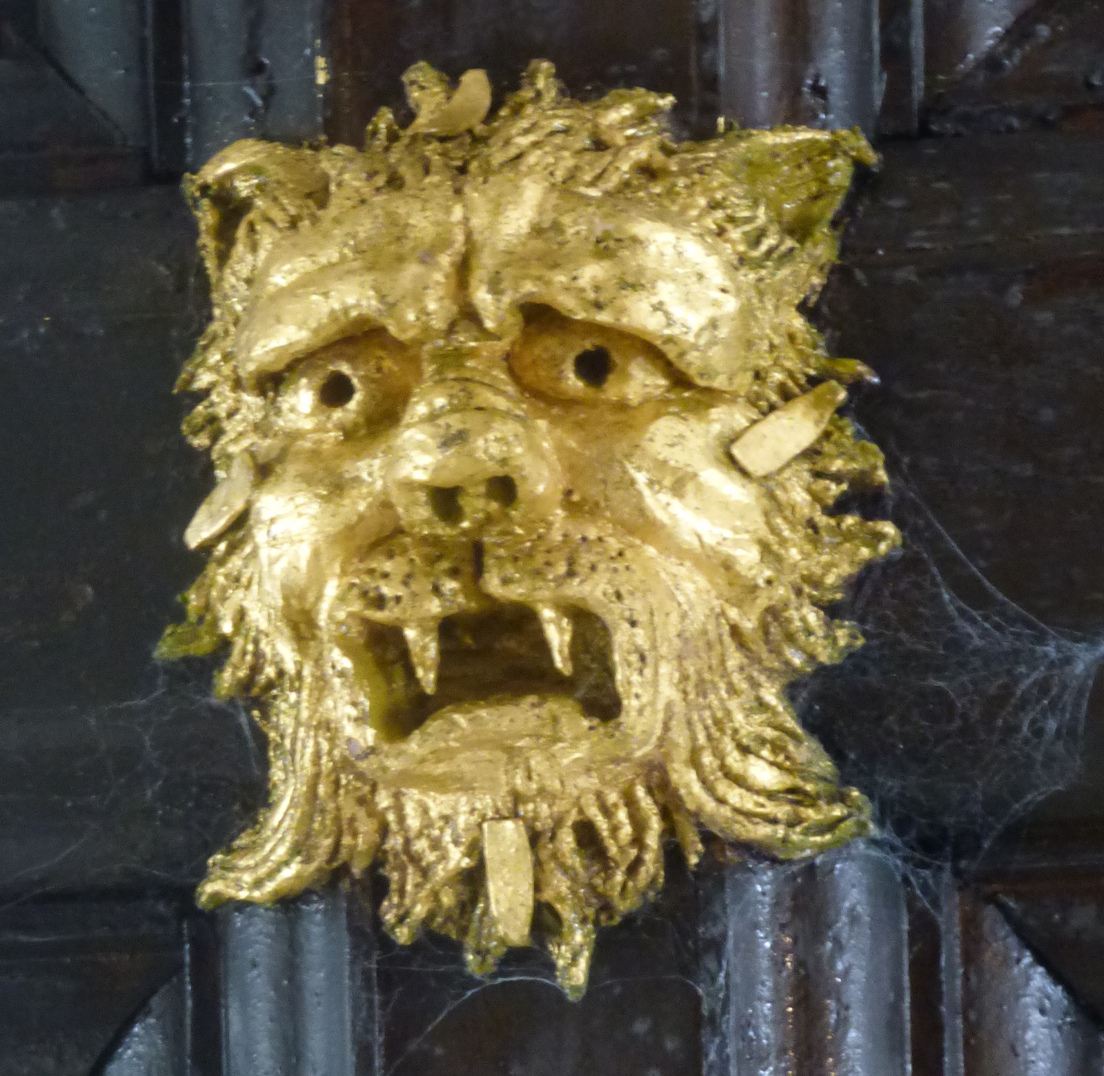
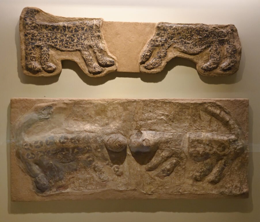
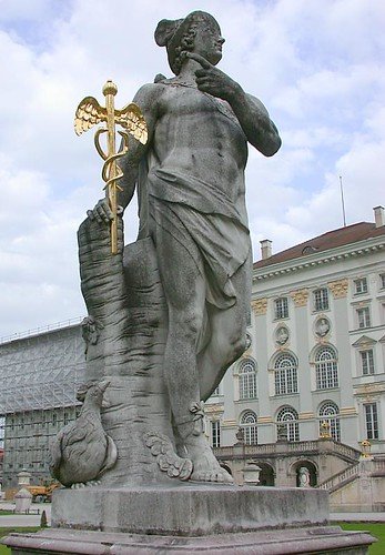
In Gaul and the Continent, the situation is different for the Gaulish god Lugus who is almost certainly the same deity behind the Irish name Lugh and the Welsh Lleu. In Roman Gaul he was routinely equated with Mercury, so most dedications show a standard Mercurial figure (cloak, caduceus, purse). A few pieces, however, carry three heads or three faces and have long been proposed—never proved—to be “triple Lugus”:
| Find |
Description |
Status |
| Reims (Durocortorum) altar-block |
Squat sandstone block with a bust on each of three adjacent faces; once labelled “Tricephalic Mercury.” |
Popularly shown online as Lugh/Lugus, but the stone bears no inscription naming the god. Identification remains speculative. (Pinterest) |
| Pillar of the Boatmen, Paris (early 1st c. AD) |
Four-sided Limestone column dedicated by Seine boatmen; one panel names Lugu[us] (fragmentary) next to a single-headed, cloak-and-purse figure. |
This is the only certain epigraphic mention of Lugus accompanied by sculpture—and it is not three-faced. (Wikipedia) |
| Tri-cephalic busts from Vertault, Condé-sur-Suippe, etc. |
Heads carved back-to-back-to-back, often with a small purse or caduceus. |
Scholars debate between Lugus, a generic “triple-form Mercury,” or a local genius. No inscriptions. |
Thus the popular tag “Lugh of the Three Faces” is continental, not Irish, and even on the Continent the connection is argued, not settled. Medieval Irish sources never give Lugh three physical heads; his epithet Samildánach (“possessor of many skills”) may have encouraged modern authors to picture him “three-faced” in a metaphorical sense.
Mercury as a Hero
The Gaulish version of Mercury absorbed far more than the quick-witted messenger of Olympus; in Gaul he carried triple functions that still included the champion/war-hero layer of Lugus. Roman observers compressed those functions under a familiar name, so the heroic edge is hidden—but not lost.
Why the Romans reached for “Mercury”
Caesar (BG 6.17) says flatly: “Of all the gods they worship Mercury most; they regard him as the inventor of all the arts, the guide of travellers, the patron of trade and gain.”
The italics echo exactly the epithets of Lugus/Lugh: Samildánach (“possessor of many skills”), guide, craftsman, guarantor of assembly. To a Roman ear that constellation shouted Mercurius. What Caesar leaves unstated—but archaeology supplies—is that this Mercury often bears:
- Weapons – short sword, spear or lightning-wand.
- War trophies – severed heads on some shrine pillars.
- Protective role – placed at gates, bridges, hillforts.
All of which are heroic, even martial, not just mercantile.
Triple forms keep the multi-aspect god intact
The tri-cephalic busts and inscriptions to Lugoues (—to the three Luguses) show how Celtic devotees held on to a three-in-one construct:
| Head 1 |
Head 2 |
Head 3 |
| Craft & eloquence (bag or purse, caduceus) |
War-champion (short sword, shield, or severed head) |
Sovereignty & justice (scale, scroll, or oak-leaf branch) |
Roman temple officials could label the whole carving “Mercury,” but Celtic worshippers still saw their own complete champion—craftsman, hero, ruler—in one statue.
The heroic flavour in continental evidence
Pillar of the Boatmen (Paris, c. AD 40): the named panel LUGU.. shows a god stepping on a prow as a protector of river crews in dangerous rapids, a practical hero role.
Clermont-Ferrand bronze tablet: dedicant thanks Mercury for victory in litigation et in bello (“and in war”), a war-aid prayer, not commerce.
Trefoil-headed spears in sanctuaries at La Tène and Mâlain are dedicated to Mercury: This weaponry points back to a warrior aspect.
So there you have it, my whirlwind tour of the Hero archetype and possible relationships with Lugh. I hope it helps fill some gaps, and raises deeper questions.


 ”
”