Archaeologists have suggested ways to organise the very varied “vitrified forts” into formal classes – especially schemes that distinguish forts Read more
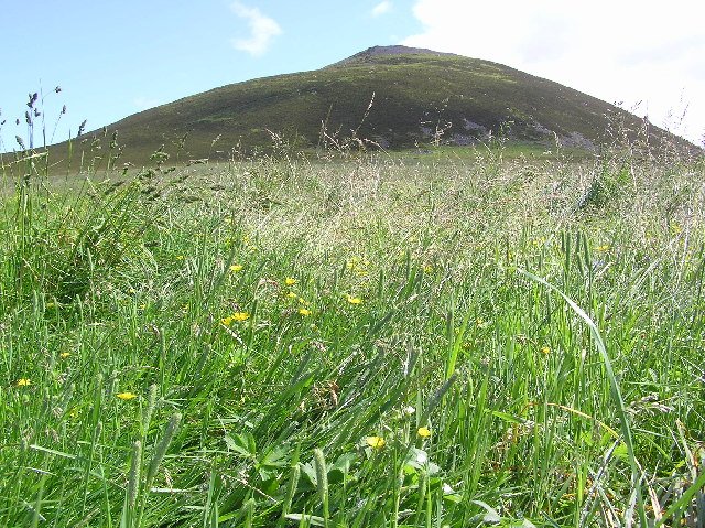
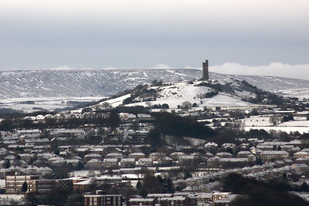
Castle Hill’s imposing silhouette hides a great prehistoric fort, Norman castle and Victorian tower. Thanks to Varley’s trenches and the Read more
Castle Hill and Almondbury from Kirkheaton
Vitrification of Hill Forts
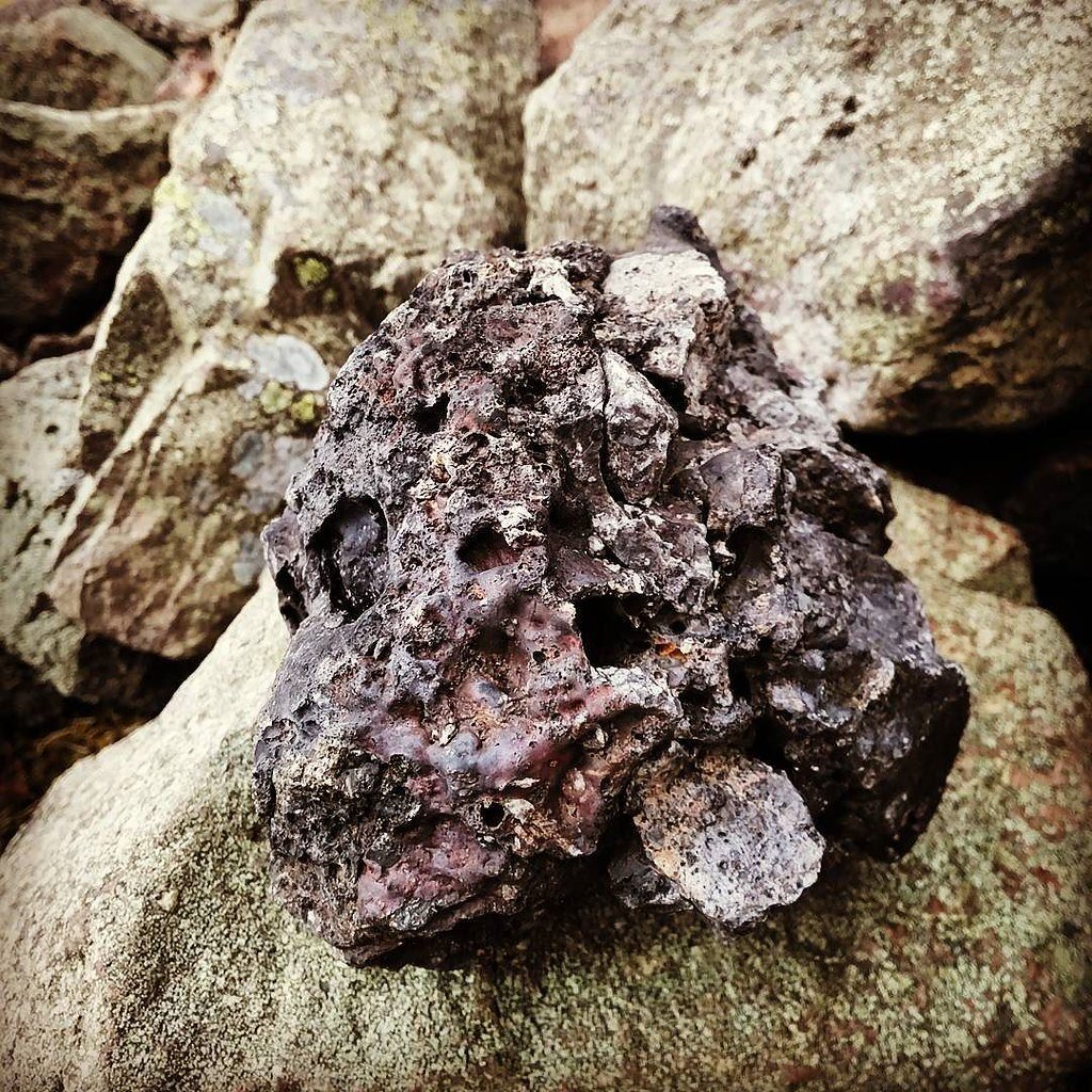
The Vitrification process
Vitrification as seen in hillforts is where the surface of the rampart has been heated to temperature that the stone has melted and bonded with its neighbouring stone. In some cases, forming a glassy surface.
The theoretical and limited practical attempts to recreate vitrification have largely been inconclusive, since significantly more effort was required to melt the rock than was expected. This has revealed several problems which our assumptions so far.
The use of imported sandstone to create the vitrified rock gives shows that the fort builder knew how to select rock specifically for its vitrification properties and shows that vitrified forts were definitely planned to be so, and therefore that other techniques will have been used to produce the desired effect. So far, science has largely overlooked this and assumed more or less simple or unplanned fires causing vitrification.
The problem lies in concentrating the heat, simply having a very large fire close to an appropriate stone face will not easily vitrify the rock. For example when a fireplace is heated, the burning temperature of wood is at it’s highest from 800 to 1200 °C, which should be hot enough to melt stone (1100 °C) but according to studies carried out by Nunnanlahden Uuni Oy, the surface of hottest stones heats up to only 650 °C in normal use. This shows the difficulty in getting a simple (but large) open fire to cause vitrification.
Some other points are worthy of mention. In the many cases of vitrification, it has been noticed that the rock applied to the rampart was of much smaller – stone fragments, it has been suggested that this was to increase the surface area of the vitrification rock and there increase the heat absorption. It also however indicated that an additional substance would have been required to hold these smaller fragments in place while they melt and adhere to the main body of the rampart.
Additionally, in some vitrified sites there is evidence that salt may have been used to increase the temperature of the fire, although this evidence is rare (France only) it may explain the largely coastal orientation of the Scottish forts.
Clearly, if ancient man were prepared to go to such lengths in preparing the surface of the rampart ready for vitrification then other techniques would have been adopted which may have been overlooked in research assumptions to date.
In is our proposal therefore that in order to vitrify a fort, ancient man left nothing to chance. Having assessed the melting characteristics of the rock (with a test burn) and acquired additional more suitable facing rock if needed. The Rampart was prepared by the application of the surface stones, together with an additional flux-like compound, which improved the adhesion and melting characteristics of the rock.
Once this was in place, the entire rampart was turned into an enormous kiln, by using clay to build a vented tunnel around the rampart, probably with multiple burning points and flues. This allows the heat to be amplified and directed towards the rampart, thus achieving the even vitrification that has been noted. Iron Age kilns were more than capable of reaching the desired temperatures.
To date there is no evidence of the kiln technique being used, since it is likely that the clay kiln will have been designed to be fully removed such evidence is unlikely to be forthcoming. However, we feel that this is the most likely method of creating a vitrified rampart since; It uses technology well known in the period; Once perfected, the technique would allow for the controlled even application of the effect which has been observed; It uses down to earth ordinary technology to provide the desired effect.
It is also likely that the preferred wood for the vitrification process would have been Oak and Yew, as these were readily available and have high burning temperatures
One other theory worthy of mention because of its historic interest rather than likely-hood is that the forts came under attack from “Greek Fire”.
Greek Fire
In ancient times, there was a substance known through writings as Greek fire. This was some sort of ancient napalm bomb that was hurled by catapult and could not be put out. Some forms of Greek fire were even said to burn underwater and were therefore used in naval battles. (The actual composition of Greek fire is unknown, but it must have contained chemicals such as phosphorus, pitch, sulphur or other flammable chemicals.)
“Greek Fire was the secret weapon of the Eastern Roman Emperors. It is said to have been invented by a Syrian Engineer, one Callinicus, a refugee from Maalbek, in the seventh century (673 AD). The “liquid fire” was hurled on to the ships of their enemies from siphons and burst into flames on contact. As it was reputed to be inextinguishable and burned even on water, it caused panic and dread. Its introduction into warfare of its time was comparable in its demoralizing influence to the introduction of nuclear weapons in our time. Both Arab and Greek sources agree that it surpassed all incendiary weapons in destruction. The secret behind the Greek fire was handed down from one emperor to the next for centuries. Rumours about its composition include such chemicals as liquid petroleum, naphtha, burning pitch, sulphur, resin, quicklime and bitumen, along with some other “secret ingredient”. The exact composition, however, remains unknown. For a thorough investigation of the weapon one can refer to Professor J.R. Partington’s book, “A history of the Greek Fire and Gunpowder”, Heffer, 1960. This volume quotes the ancient authorities extensively, with an excellent commentary. It also examines ancient and modern theories on the composition of the chemicals used in the Greek Fire. This is considered the most up-to-date source on the subject. “
If we could run Child’s experiment again
Project Brief (Version 0.1) — Experimental Reconstruction of Hill-Fort Vitrification
Purpose & Vision
Recreate a controlled-scale rampart fire that reproduces the melt textures, magnetic signatures and labour demands observed in Iron-Age vitrified forts.
The experiment should answer how, why and under what boundary-conditions vitrification is achievable.
Key Research Questions
Thermal window — What minimum temperature–time curve is required for continuous glass formation in different lithologies?
Construction variables — How do timber-lacing style, wall thickness and outer revetments influence peak temperature and melt spread?
Fuel logistics — What fuel mass, species mix and draught strategy deliver the target thermal window at fort-scale?
Magnetic & mechanical outcomes — Does the experimentally produced melt replicate archaeomagnetic directions/intensities and post-fire wall strength seen in the field?
Environmental footprint — How much woodland and greenhouse gas output did ancient firings entail?
Selection Criteria for the Experimental Build
Criterion
Rationale
Target Specification
Lithology
Must represent the main natural classes
Basalt/dolerite (MI) and quartz-sandstone (QS) blocks sourced within 5 km
Construction class
Recreate the dominant timber-laced core (TLC) and a stone-only control
2 test walls, 6 m long × 2 m high × 2 m wide
Layout proxy
Inner-wall firing scenario most common (D-IV)
Single wall surrounded on three sides by a low earthen berm to mimic outer ring/wind-break
Fuel type & supply chain
Reflect local Iron-Age woodland
Mix of air-dry oak, birch and pine; scalable bundles pre-weighed
Site logistics
Safety, permits, research infrastructure
Disused quarry or forestry compound with road access, water supply, 100 m safety buffer
Experimental Variables & Control Set
Fuel-load series (10 t, 20 t, 30 t per wall)
Draught regime (natural chimney vs. forced-air via electric blowers simulating bellows)
Moisture content (15 % vs. 25 % wood MC)
Tapered firing (progressive ignition from base) vs. blanket firing (multiple ignition points)
A full factorial is unrealistic; prioritise Lithology × Fuel-load × Draught (i.e., 12 runs over two seasons).
New analytical & field-survey tools now on the bench —and why they change the game
Past limit (pre-2000)
2020s capability
Why it matters for a vitrification experiment
Hand specimen & thin-section only to see melt texture
Micro- & Nano-CT (Voxel < 1 µm) reveal 3-D pore networks, glass bridges and surviving timber voids without slicing the block. (Oxford Academic)
Quantifies true melt fraction and pinpoints the hottest zones before destructive sampling, letting us correlate temperature logs with glass continuity.
X-radiography gave 2-D shadows
Neutron tomography penetrates heavy silicates yet highlights light elements (charred wood, water). (ResearchGate, Artnet News)
Sees internal charcoal and moisture paths—critical for modelling draught and Steam-burst fracturing.
Fuel-efficiency metrics: DTS, CFD and anthracology combine to turn “20 t of wood” into precise energy balances tied to specific species mixes.
High-resolution dating: Single-grain OSL and Bayesian SV curves can test whether the inner and outer walls burned days, decades or centuries apart—something impossible with 1970s TL.
Mechanical relevance: Real-time AE + micro-indentation links melt fraction to strength gain, showing whether vitrification ever genuinely improved defence.
Together these tools mean the 2020s reconstruction can move from qualitative replication (“it looks like a vitrified wall”) to quantitative, testable physics tied directly to sourcing, labour and chronology.
Core hypotheses for why Iron-Age builders vitrified ramparts
(ordered by the weight of present archaeological, experimental and contextual evidence)
Rank
Short label
One-line statement of the hypothesis
Key empirical predictions
1
Destructive assault / clearance fire (D)
Enemy or fleeing defenders set the wall alight during a violent episode, turning timber-laced rubble into slag.
Mixed destruction debris; weapon points fused into glass; rapid single firing; occupation gap often follows.
2
Ritual closure / prestige display (R)
Incumbents stage a spectacular “closing ceremony”: piling fuel inside the core to create a gleaming, ever-visible ruin that advertises power or sanctifies abandonment.
Fuel stacked on wall top or interior; offerings sealed under glass; later reoccupation or ritual deposition on vitrified surface.
3
Structural strengthening (S)
Builders melted the core deliberately to fuse blocks, producing a harder, monolithic wall.
Melt concentrated at load-bearing joints; little destruction debris; no architectural hiatus; measurable post-fire strength gain.
4
Concealment / scorched-earth withdrawal (C)
Refugee groups destroy their stronghold to erase material identity and deny the enemy clues; valuables are melted or removed.
Thorough melt, deliberate stripping of artefacts, synchronous hoard burial or crucible slag, long occupation gap.
5
Creative construction (Cr)
Vitrification took place before the fort was ever occupied—essentially a high-tech building method.
Glassy lining on inner face only; pristine occupation layers later; no destruction deposit; radiometric date on melt predates settlement.
6
Incidental natural fire (I)
Local wildfire or lightning ignited the timber core accidentally.
Highly localised vitrification; no patterned fuel loading; variable timber moisture; occupation continues almost uninterrupted.
Should the experimental wall replicate a known fort-type or invent a new hybrid?
Short answer: build (at least) one wall that duplicates a well-documented exemplar—and Almondbury (Castle Hill, Huddersfield) is an excellent candidate for the “difficult-to-vitrify” end of the spectrum—then pair it with a mafic, high-vitrifiability wall (e.g., Dunagoil-style).
Why Almondbury specifically makes sense as the refractory-stone case
Timber-laced core on quartz sandstone – the classic combination that should resist continuous melt, perfect for testing minimal vs. maximal fuel scenarios.
Partial burn evidence – Varley recorded a severe fire episode but only patchy vitrification; reproducing (or beating) that threshold is a real scientific goal.
Large archive – sectional drawings, charred-beam casts and radiocarbon series are already digitised.
Logistics – Local quarries still extract Grenoside & Millstone Grit, so sourcing identical blocks within a 5 km haul is feasible.
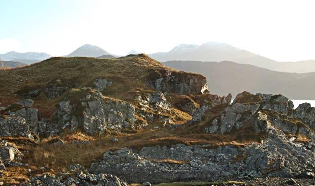
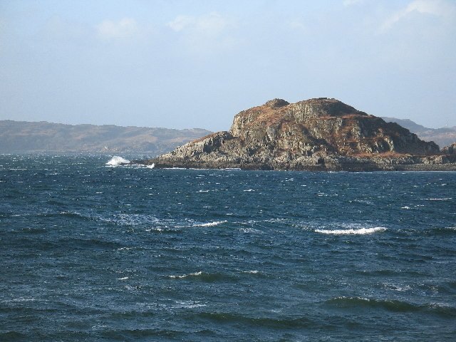
A 30 m-high volcanic promontory on the south-west coast of the Isle of Bute, defended naturally by cliffs on N & W and overlooking the Sound of Bute. The only easy approach is from the landward ESE shoulder. (hillforts.arch.ox.ac.uk)
Geology
Columnar‐jointed basalt/dolerite sill → very low solidus, melts readily; smashed columns are still visible in the vitrified curtain. (Britain Express)
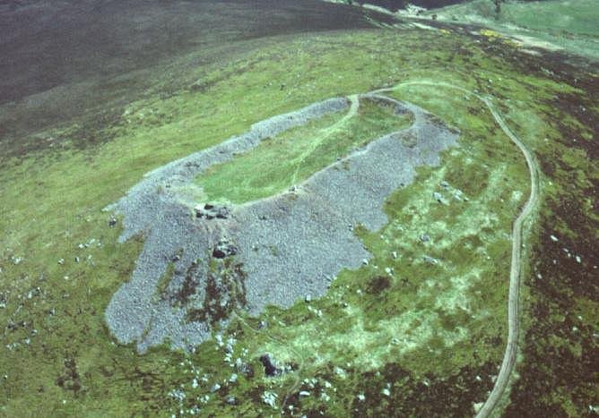
Layout
Roughly oval summit (≈ 110 m × 45 m). Single curtain wall c. 3.6 m thick; small annex “Little Dunagoil” and a cliff-edge outwork protect subsidiary knolls to E & NE.
Vitrification
South & south-west stretches show massive, glass-welded core; elsewhere the core is reddened but not fully molten. Basalt blocks fuse into black-green slag sheets several decimetres thick.
Construction class
Clear beam-socket shadows and charcoal lenses indicate a timber-laced core (TLC) rampart.
Key finds
Bronze-Age clay spear-butt mould, Early La Tène 1c iron brooches, rotary quern fragments, bone pins, flint knives; material now in Bute Museum. (Cambridge Core)
Excavation history
1913–19 Ludovic Mann trial trenches; 1942 RCAHMS emergency survey (Graham & Childe); 1968–69 re-clearance; 1994–95 full EDM & plane-table survey by Univ. of Edinburgh (D. Harding). All archives digitised at Canmore and Bute Museum. (Trove Scotland)
Dating evidence
Diagnostic La Tène artefacts suggest primary use c. 400–200 BC; no radiocarbon or archaeomagnetic samples have yet been published.
Current access
Open pasture—public footpath from Dunagoil Bay car-park; vitrified blocks visible in situ (care on slippery glassy faces).
How Dunagoil scores on the draft classification model
TLC Timber-laced core
T Thorough vitrification (south flank)
D? Probably destructive firing (no clear closure deposits, but heavy collapse debris)
LIA Artefact dating places event in the Late Iron Age