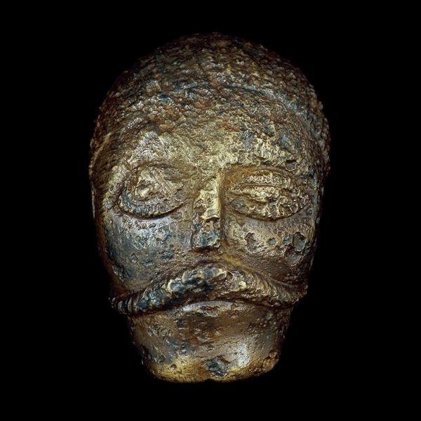
Celtic Head from Witham, 2nd c B.C. (British Museum) "Celtic" carved heads are found throughout the Read more

This timeline is focussed on the British Celtic culture and those cultures which had influence on the British Celts. It Read more
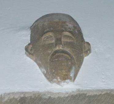
An analysis of head carvings in a local area In many churches throughout England there are carvings of possible pagan Read more
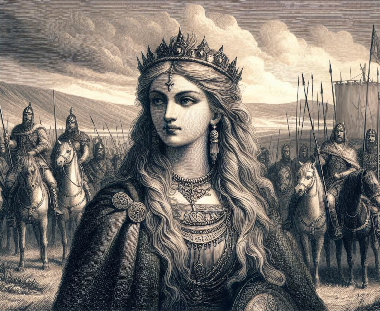
Yorkshire, and much of northern Britain was also ruled by a queen, the most powerful ruler in Britain in fact. Read more
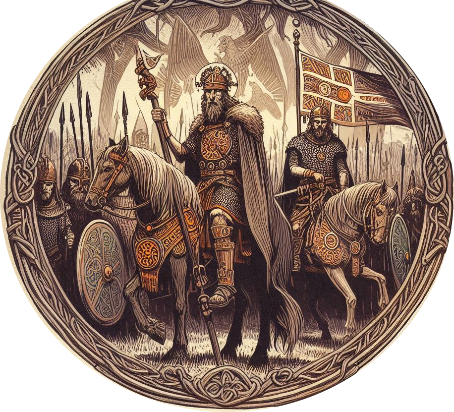
Caratacus was highly influenced by the Druids, and both he and his brother Togodumnus were among the leading lights of Read more

Quintus Petillius Cerialis Caesius Rufus was the son-in-law of Vespasian Cerialis and became Governor of Britain in AD.71; his instructions Read more

Ask anyone to name a famous Roman character, and the name of Julius Caesar is sure to be the most Read more
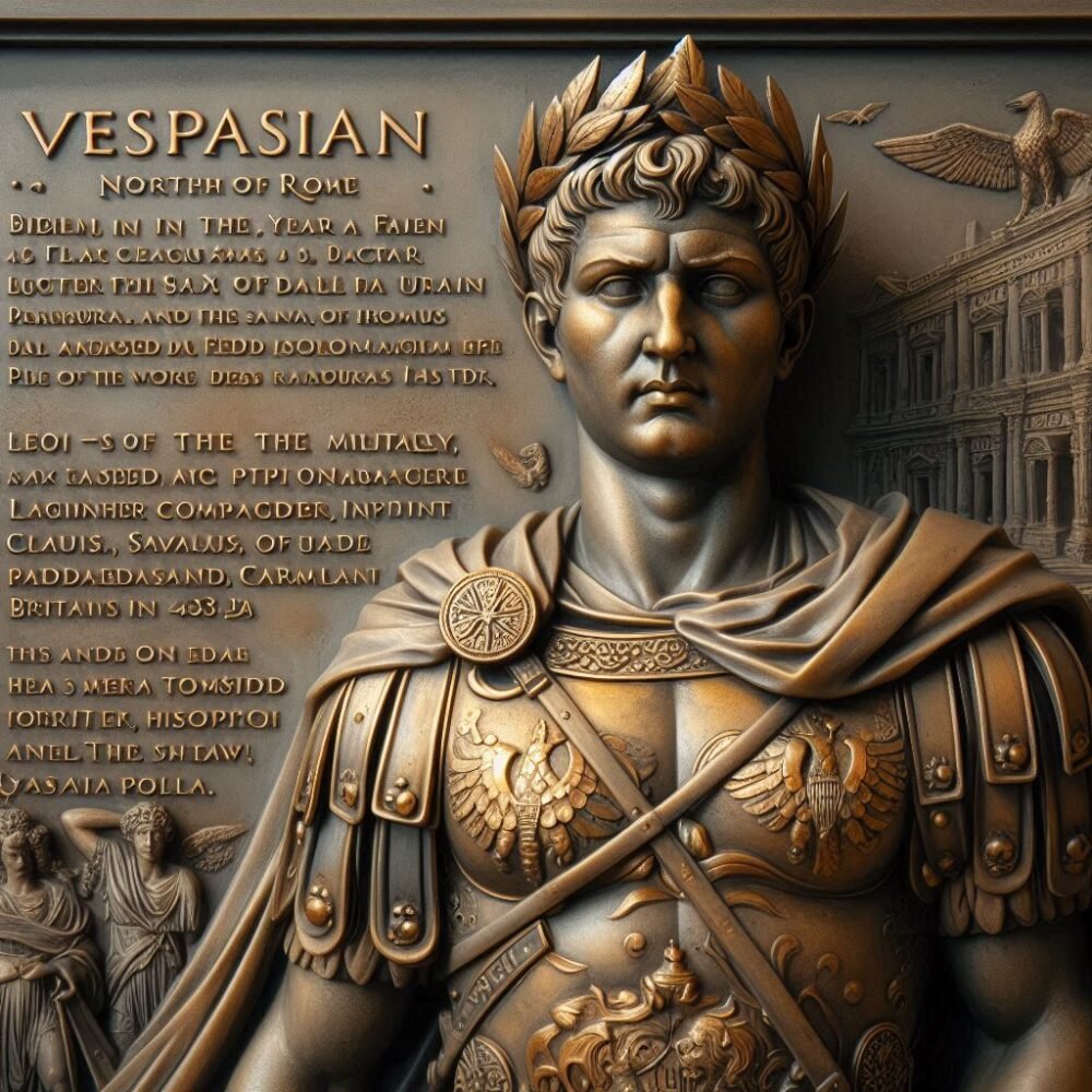
Born in the year 9 at Reate, north of Rome, Vespasian was the son of a tax collector, Flavius Sabinus Read more
Suetonius wrote of him: He was very handsome and most graceful at all stages of his life, although he cared Read more
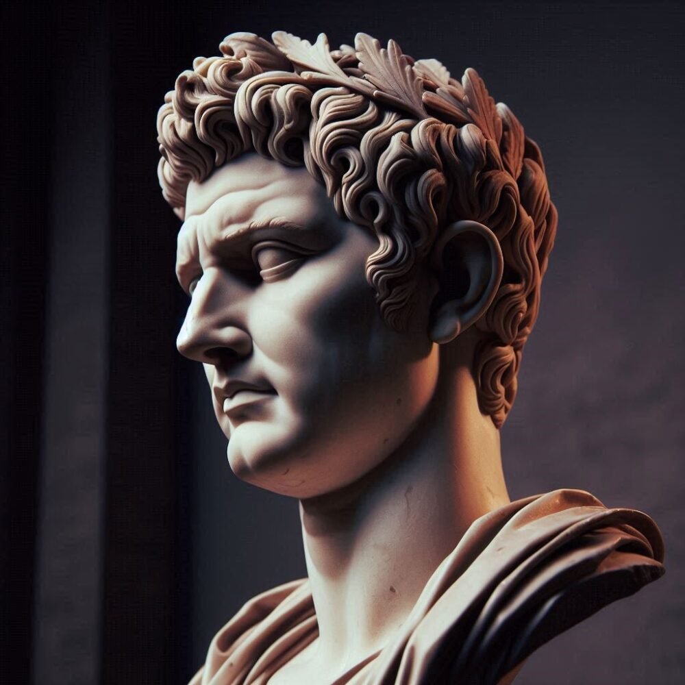
Tiberius Claudius Nero Germanicus was born Lugunum in 10 BC, the youngest son of Nero Drusus, brother of Tiberius. He Read more
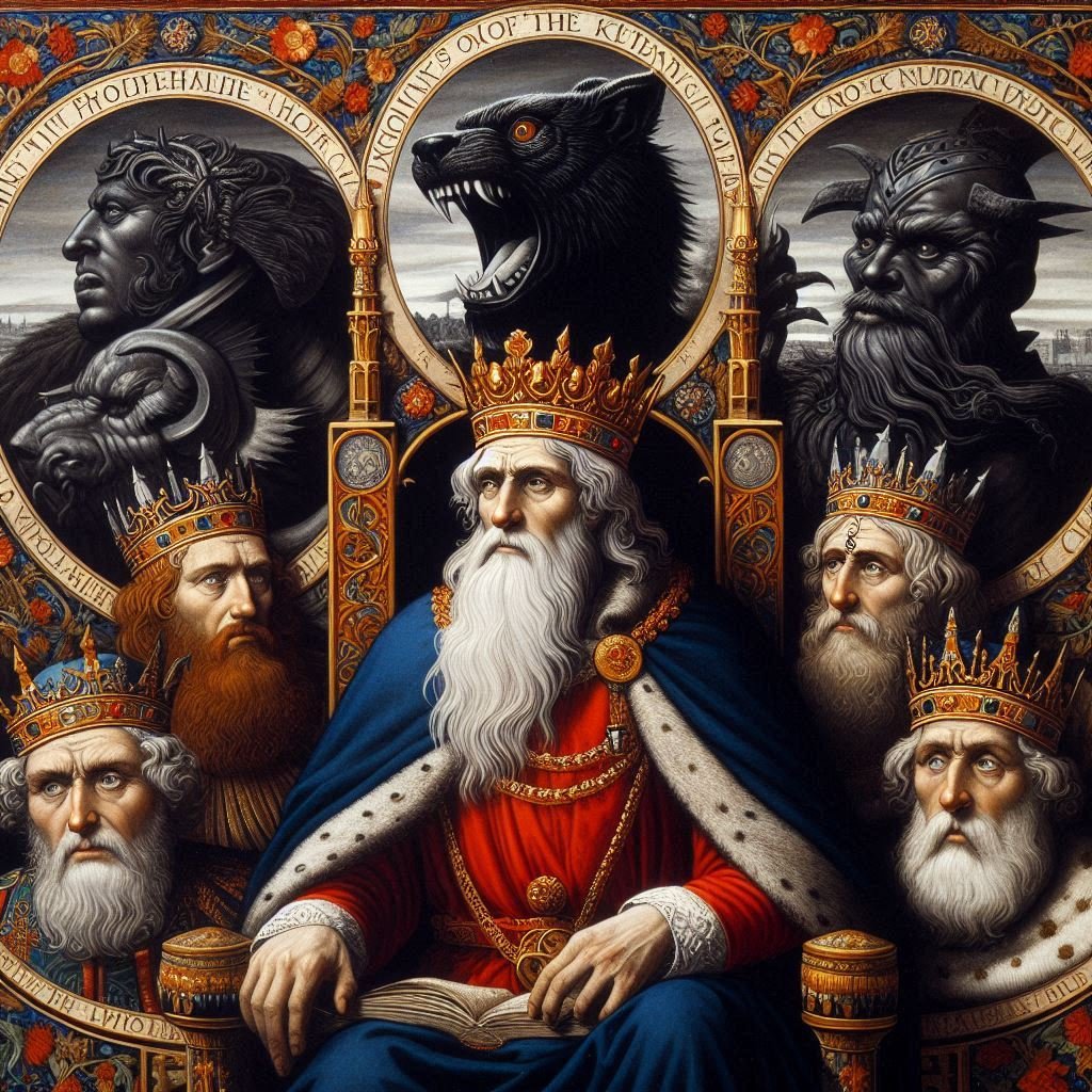
Geoffrey of Monmouth's Kings of Britain includes a number of unknown potential kings, as well as some recognised as existing, Read more

Many Celtic deities seem to have been associated with aspects of nature and worshipped in sacred groves. Some appear in Read more
by Roland Comte
Translated from the original French version by an Internet Engine – sorry!
– SCOTLAND (10 sites)
1.1. Year Cnap (arran Iles) (source: site internet of the arran Iles);.
1.2. Barry Hill (Allyth, Perthshire) (” All that remains of this vitrified strong are has massive tumbled stone wall and subsidiary ramparts”, site internet alyth);
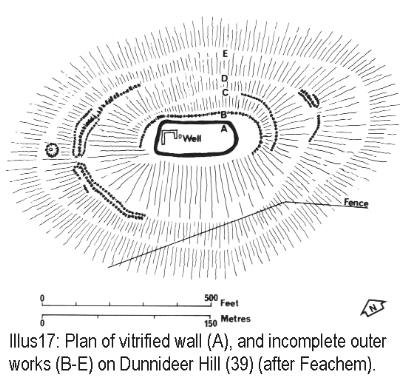
1.3. Craig Phadrig, inverness department (« Two vitrified walls enclosed year area 75M by 25M. The inner wall
stands 1.2m high one the inside”, site internet easyweb.easynet);
1.4. Dun Deardail (towards Lochaber, west of Scotland) [source: site internet of Lochaber];
1.5. Dun Lagaidh, commune of Ullapool, department of beat up & Cromarty) (« Massive stone rampart of the 1ST millenium BC, now vitrified and so originally timber-laced (…)” [source: HAI];
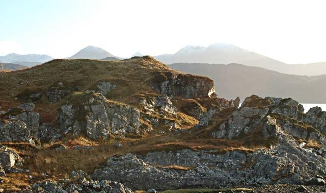
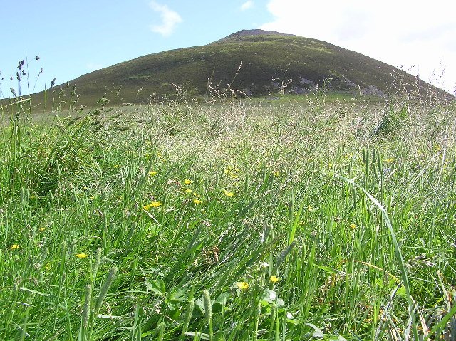
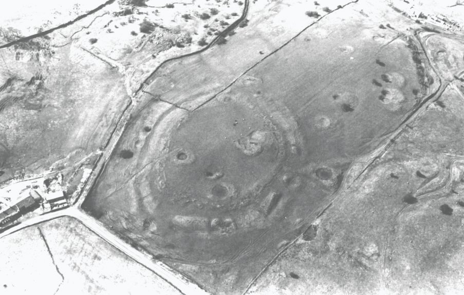
1.6. Finavon (Angus) [Source: CHILDE, 1935];
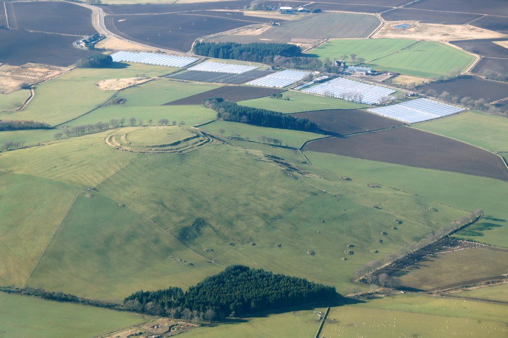
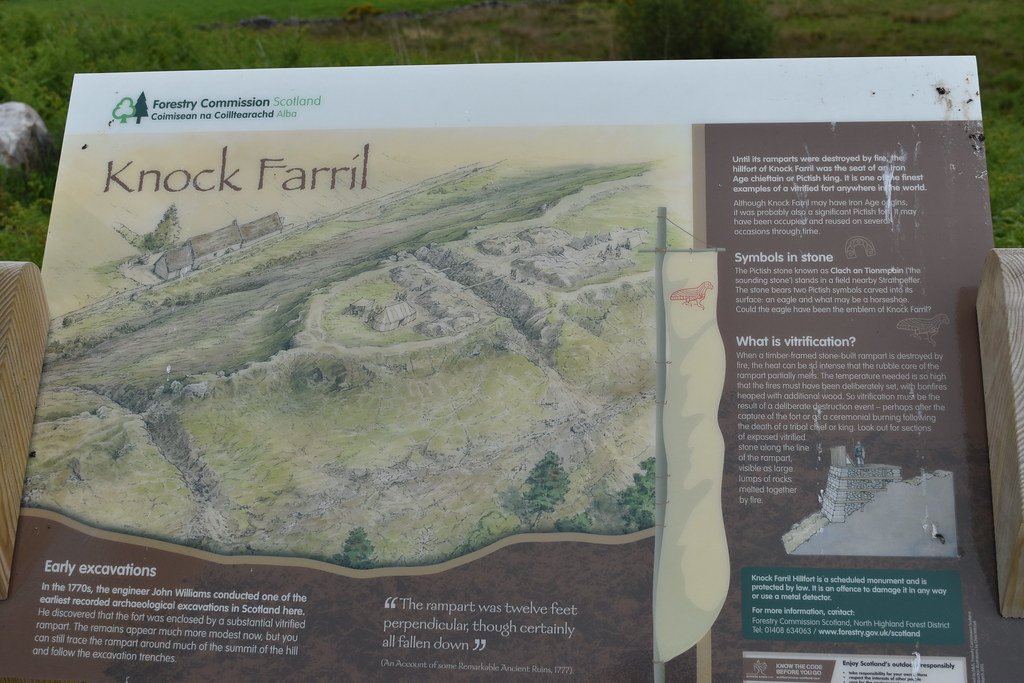
1.7. Knock Farril, commune of Strathpeffer, dépt. Beat up & Cromarty, (Oblong strong hilltop of the 1ST millenium BC, its stone rampart heavily vitrified so presumably originally laced with timber »; Source: HAI);
1.8. Tor a’Chaisteal Dun, arran Ile (Ireland);
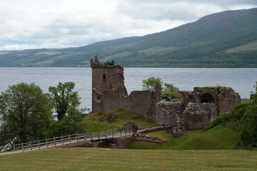
1.9. Urqhart Castle (close to Inverness);
1.10. White Caterthun (in passing signaled by RALSTON, 1992 as being vitrified about the French site of the Camp of Caesar to CHATEAUPONSAC, Hte. -Vienne).
2) IRELAND (1 site)
2.1.Tour of Toriniz, Tory Island (Ireland). See this that some is said in the text above..
3) FRANCE (more than 70 inventoried sites, of which at least a 20th vitrified ones)
3.1. Ally (03)
3.1.1. BEGUES: Oppidum of Stutterers (« vitrified Wall », RALSTON, 1992). A visit, in May 2000, we allowed to obtain the proof of the vitrification. Removed Echantillons.
3.2. Cantal (15)
3.2.2. COREN: Puy of the Fage [RALSTON (1992), p. 124]. Possible confusion with The fage-montivernoux (Lozère).
3.2.3. ESCORAILLES: Not any place says. [RALSTON (1992), p. 124].
3.2.4. THE BEND: « The Castle Gontier ». Attention! : Risk confusion with The Bend, close to argentan (Decorates).
3.2.5. MAURIAC (has) : « Old Castle », escoalier hameau* (« Certain indices leave to think that the two communes neighbor can have each a pregnant vitrified one », RALSTON, 1992). * Possible Confusion with Escorailles (to see above).
3.2.6. MAURIAC (b)
3.2.7. MAURIAC (c)
3.3. Charente (16)
3.3.1. MOUTHIERS-ON-BOEME: Not any place says [RALSTON (1992), p. 124].
3.3.2. VOEIL AND GIGET: « Camp of the English or Rock Lasts » (« calcination Tracks on the whole length of the talus, 210 m of long one, 5-6 top m and 25 m of wide one. The surface of this blocked éperon covers 3 hectares env. », RALSTON, 1992). Well that one speaks only of « calcination », the toponyme of « Rock Lasts » could be an index of vitrification.
3.3.3. SOYAUX: « Camp of Recoux ». [RALSTON (1992), p. 124].
3.4. Dear (18)
3.4.1. THE GROUTTE: « Camp of the Murettes » (or « of Caesar »). « SPREADS ITSELF on 4 hectares. » [RALSTON (1992), p. 124].
3.5. Corrèze (19)
3.5.1. Lamaziere-basse: « Field of the Châtelet » to the place says The Bessades (« vitrified Rocks in the éboulement to the eastern extremity of the internal wall. Other vitrified gneiss, not only in the éboulis of the wall but equally to the eastern extremity of the wall to the exterior one. The vitrification seems to be limited to this party of the site », RALSTON (1992), pages. 46-47. In his bibliographie, the author relates back to VAZEILLES: vitrified Station with vitrified wall of the Châtelet, lamazière-basse commune (Corrèze).)
3.5.2. MONCEAUX s/dordogne: « Puy of the Tower » or « Turn » (« A rock pad vitrified », RALSTON (1992), pages. 49-53).
3.5.3. MONCEAUX S/ DORDOGNE: « Puy Grasset » or « Granet » to the place says « The C (h) astel » or « the Chastelou » to the town of Raz. « Some tracks of visible vitrifications in the rocks schisteuses of the summit of the motte (that would be medieval era ». « Desbordes describes the pregnant one as vitrified and, doubtless, medieval ». [RALSTON (1992), p. 53]
3.5.4. ST. GENIEZ-o-BLACKBIRD: « Puy of Sermus » or « Old Sermus ». (« THE principal INDEX of fortifications consisted in a wall section vitrified, high of 1,5 m and long of 3 m, situated on the northwestern side of the site where the access was the easiest one. (…) The defenses reconnaissables consisted in two sections of vitrified walls with an artificial slope to the exterior one. (…) A search on the northwestern side showed that the vitrified
wall was constructed directly on the rock, that presented some signs of a superficial vitrification. », RALSTON, 1992.)
3.5.5. (?) ST. PRIVAT: « Camp of Srmus » (or « Sermus ») [MARCILLE, p. 17]. It must be a matter of a confusion with the preceding one.
3.6. Armor coasts
3.6.1. PLEDRAN: Camp of Péran [MARKALE (1997), pages. 133-135. Visited site in July 1998. The vitrification is obvious on the body of the site, that perfectly was released at the time of our visit. The rock is melted and combined in of big soldered pads together. Removed Echantillons. See this that we some say higher.
3.7. Coast of now (21)
3.7.1. BOUILLAND: « The Châtelet ». Without other precision.
3.7.2. CRECEY-ON-TILLE: « fountain Camp Brunehaut » [RALSTON (1992), p. 124. It does not say if it is vitrified or no].
3.7.3. Chambolle-musigny: « Pregnant of Groniot » (or « Gromiot »). Without other precision.
3.7.4. ETAULES: « The Châtelet » (« Remain charred beams », RALSTON, 1992). One does not speak any vitrification. MARCILLE (1999), p. 17 city « The Easel ». We think that it must be a matter of an erroneous graphie.
3.7.5. FLAVIGNEROT: « Camp of Caesar » says Pregnant so of the Mount Africa. [RALSTON (1992), p. 125].
3.7.6. Gevrey-chambertin: « Pregnant of the Castle Fox » [RALSTON (1992), p. 125].
3.7.7. MESSIGNY: « Pregnant of Rock Castle ». Not any other precisions.
3.7.8. PLOMBIERES-THEM-DIJON: « Pregnant of Wood burnt » [RALSTON (1992), p. 125]. The toponyme of « Drinks Burned », met on of other sites, can be the confirmation of a vitrification.
3.7.9. VAL SUZON: « The Châtelet of Val Suzon or Fountain of the Cat ». « Situated just opposite the etaules Châtelet, on the other side valley » [given as being vitrified by MARCILLE (1999), p. 17]. (« Puts to bed burned », according to RALSTON (1992).
3.7.10. VELARS s/ouche: « Pregnant of Our Lady of the etang ». Given as vitrified by MARCILLE (1999), p. 17.
3.7.11. VIX: « Mount Lassois » (« The ‘raised earth’ southern (…) seems to have been constructed on a burnt level on which one rest rocks sometimes rubéfiées or charred », RALSTON, 1992). One does not speak any vitrification. Thus, maybe, that of other sites according to the studies of Nicolardot (quoted by RALSTON, 1992).
3.8. Hollow (23)
3.8.1. AUBUSSON: « Camp of the Chastres ». Tracks of vitrifications [RALSTON (1992), p. 70].
3.8.2. & 3.8.3. BUDELIERE: « Promontoires of St. Marien » and of « Ste. Radegonde ». We returned ourselves on the promontoire of Ste Radegonde in 1999 from the indications of RALSTON but the site being very overgrown, we were not able to observe vitrifications.
3.8.4. JARNAGES: Pregnant under the name of « Castle ».
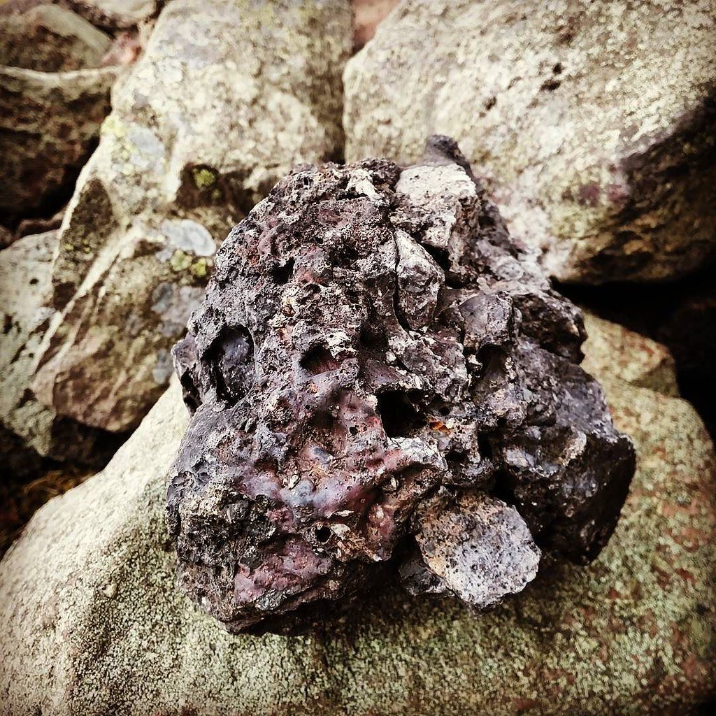
3.8.5. PIONNAT: Oppidum to the town* of « Châteauvieux ». [RALSTON (1992), pages. 75-79]. * The hameau of Châteauvieux is distant Pionnat of several km. Oval pregnant of 128 length m axial. Despite the embroussaillement of the site, our visit of the summer 1999 allowed us to confirm the existence of an important one, well visible vitrification and indiscutable: more again than to Péran, the rocks are melted and combined between they. One sees even tracks of drips, as in the case of wash volcaniques. The heat had to be of an extreme intensity. Certain descriptions of the site talk about traces of ovens to limes or of ovens to metals. We think that it is a matter of a bad interpretation of the observations done by persons that never had not seen vitrifications. For us, there is no doubt that Pionnat shows obvious tracks of vitrifications. Removed Echantillons. Another site, « City of Ribandelle (or Ribaudelle ») would face for him.
3.8.6. STE. FEYRE: « Puy of Gaudy ». Visited to the same era. Same observation that to Pionnat but the degradation of the wall and his embroussaillement did not allow us to note evident tracks of vitrifications. [RALSTON (1992); bases Mérimée].
3.8.7. ST. GEORGES OF NIGREMONT: « The Wall ones » (or « the Muraud »). [RALSTON (1992), pages. 80-81. Despite the indications of RALSTON, completed by collected indications on the spot with the inhabitants that knew the existence of the site, we were not able to identify the location of the oppidum of the Wall ones. They counseled us to contact Mister EUCHER to Rouzelie, that had searched the site, this that we were not able to do.
3.8.8. THAURON: Town. Disappointing visit: useless to look for tracks of vitrifications. The site totally was destroyed by the anarchic extension of the town, installed on the oppidum and nothing is not done to preserve this that could some to exist.
3.9. Dordogne
3.9.1. PERIGUEUX: Pregnant of the « Camp of the Boissière » situated on the one of the buttresses of the upright shore of the isle opposite Périgueux. Do not to confuse with Périgneux (Loire).
3.9.2. ST. Excideuil MEDARD: « Castle Sarrazi » to Gandumas (« at least two distinct and deeply vitrified works are preserved (…). The tracks of the original position of the poutrage were recognized in the vitrified mass (…). » [RALSTON (1992)]. Same observation to Péran.
3.10. Doubs (25)
3.10.1. MYON: « Châtelet of Montbergeret » [RALSTON (1992), p. 126].
3.11. Finistère (29)
3.11.1. Ergue-armel: « Berg-ar one-Castle » [RALSTON (1992), p. 126]. Nothing indicates only this site is vitrified.
3.11.2. HUELGOAT: « arthus Camp ». « Secondary massive Wall, dated no, recovering a murus gallicus type Avaricum. » [RALSTON, 1992, p. 132]. Visited site during the course of the summer 1998. Unfortunately it spread of the site, besides very overgrown, did not allow us to study so certain parties showed tracks of vitrifications.
3.11.3. Lostmarc’h (close to CROZON). [the Celts, p. 586].
3.12. Ille-and-Villaine (35)
3.12.1. . 126.
3.13. Jura (39)
3.13.1. SALINE: « Camp of the Castle-on-Saline ». « Charred Material on about 4 m of long one on the side west of the wall préhistorique (…). » [RALSTON (1992), p. 127].
3.14. Loire (42)
3.14.1. PERIGNEUX: « Peak of the Violet » (« A plateau to 650 altitude m is described as partially enclosed by of weak walls and vitrified pads », [RALSTON (1992), p. 127]. Do not to confuse with Périgueux (Dordogne).
3.14.2. ST. ALBAN-THEM-WATERS: « Châtelus » [or « Châtelux », with RALSTON, 1992, obviously erroneous graphie]. (« Vitrified rediscovered Materials on the spot », RALSTON, 1992). Superficial visit of the site in May 1999, the brushlands and the foams recovering the rocks prevented me from identify all trace of vitrification. That does not want to say that it not there in have. On the spot, the people know the site under the name of « glass Castle », name that appears me sufficiently significant for that one can admit this site in the list of the vitrifications (to see MARKALE).
3.14.3. VILLEREST: « The Burnt Castle » to Lourdon. Visit to Villerest in May 1999. I was not able to attain the site but the city hall communicated me the result of searches effectuated by Stéphane Boutet (quoted by MERCHANT, 1991), that confirms the existence of a « vitrified wall » and the comes close to the « glass Castle » of ST. ALBAN-THEM-WATERS; this text indicates in addition: « This wall type vitrified is not unique in our region ». About name « glass castle », even notices that au-dessus, see this that some says MARKALE.
3.14.4. ST. CAP-OF THE-QUARTER (region of ROANNE) : « Oppidum of the Ensconce (or Quarter) ». We returned ourselves on the spot in May 1999, but we were not able to situate the place of the oppidum..
3.15. Batch (46)
3.15.1. CRAS: « Murcens ». [RALSTON (1992), p.127]. 3.15.2. LUZECH: « THE impernal ». [RALSTON (1992), p. 127].
3.16. Lozère (49)
3.16.1. THE fage-montivernoux: « Puy of the Fage ». [RALSTON (1992), p. 127]. Attention: possible confusion with « The Puy of the Fage » in the Cantal (commune of COREN). Often these remarkable sites were taken as limit of several communes, this that can induce granting errors to such or such commune.
3.17. Mayenne (53)
3.17.1. LOIGNE-ON-MAYENNE: « The Caduries ». Vitrified [RALSTON (1992), p. 127].
3.17.2. ST. JOHN-OF-MAYENNE: « Pregnant of Castle meignan ». [RALSTON (1992), p. 127; MARCILLE (1999), p. 17].
3.17.3. STE. SUZANNE: « The Castle ». It seems that we have to deal with two distinct sites: « The Castle » and « The Camp of the English ». According to RALSTON (1992) : « The vitrified material originating of this commune comes from foot of the castle of Ste. Suzanne and no of the Camp of the English ».
3.18. Meurthe-and-Moselle
3.18.1. CHAMPIGNEULLES: « Pregnant of the Fourasse » (or « Tourasse). Tracks of vitrifications according to RALSTON (1992), p. 127. MARCILLE (1999).
3.18.2. ESSEY-THEM-NANCY: « mounds It (or pregnant) Ste. Geneviève » (« fire Tracks of the again observable walls on the side west of the site », RALSTON, 1992). One does not speak any vitrification.
3.18.3. MESSEIN: « The City », or « The affrique Camp » or « the Old Market » (« calcination Tracks », RALSTON, 1992). One does not speak any vitrification.
3.18.4. Sion-couvent: Said Place specified no. RALSTON (1992) talks about « calcination Tracks », no of vitrifications.
3.19. Morbihan
3.19.1. Landevant-kervarhet: « Kervarhet » (« Pregnant of a diameter of 200 Mr. Tracks of vitrification », RALSTON, 1992).
3.20. Moselle (57)
3.20.1. LESSY: Not any place says [RALSTON (1992), p. 128].
3.21. Nièvre
3.21.1. THE MACHINE: « Pregnant of the Old Castle » or « Quoted Barbarity ». Certain Vitrification [MARCILLE (1999), p. 18, with a plan].
3.22. Oise
3.22.1. GOUVIEUX: Camp of Caesar (« calcination Tracks », « massive secondary Wall raised above a wall to internal burnt poutrage: the latter was not dated. » RALSTON (1992), p. 132. One does not speak any vitrification.
3.23. Decorate (61)
3.23.1. ARGENTAN: Strong vitrified. It can himself that it is a matter same site that the following one. 3.23.2. THE BEND: « The Top of the Castle ». (« Spread Tracks of an excessive combustion, notably vitrified pads and rocks of revêtement impaired by the heat », RALSTON, 1992).
3.24. Puy-of-dome (63)
3.24.1. and 3.24.2. CHATEAUNEUF-THEM-BATHS: « Mountain of Villars » (« The vitrified material comes from a long wall of 14 m that forms the one of the sides of a rectangle of 7 m X’S 15 m crowning a mounds rocks », RALSTON, 1992). A visit on the spot in May 2000 did not allow us to find the site but an inhabitant of the hameau of Villars, to that requested us our way, knew the existence of « melted rocks ». It indicated us that it there has not had a single site, on which one one found these rocks, but two. According to its explanations, we understood that it was a matter of two Oppida, near of each one other.
3.25. High rhin (68)
3.25.1. HARTSMANWILLER: « H artmannswillerkopf ». « Traces of a pregnant one vitrified of era protohistorique existed to the Hartmannswillerkopf but were destroyed during the battle of the Old Armand in 1914 and 1915. » [Bases Mérimée of the ministry of the culture].
3.26. High saône (70)
3.26.1. BURGUNDIAN-THEM-MOREY: Not the place says. « Site of 3 hectares. Calcination tracks in a talus of thick rocks of env. 3 meters (One does not speak any vitrification) [RALSTON, 1992, p. 129].
3.26.2. MACHEZAL* : Crêt Chatelard (« vitrified Material but it is not certain that it foolish in report with a vitrification » RALSTON, 1992). * Close to CHIRASIMONT, to the s/e of Roanne. Another source indicates also a « tumulus burgonde and a grave to the vitrified walls ». It is a matter without doubts the same site.
3.26.3. NOROY-THEM-JUSSEY: Not any place says: « Pregnant of 2,5 hectares. Calcination tracks of the fortifications. » [RALSTON (1992), p. 129]. One does not speak any vitrification.
3. 27. Come (86).
3.27.1. ASLONNES: alaric Camp (« Pautreau seems to admit that this fortification was charred », [RALSTON (1992)].
3.27.2. Chateau-larcher: « Site of Thors or Thorus ». « Strong vitrified; the ruins were not searched. »
3.27.3. QUINCAY: « Camp of Séneret (or Céneret) » between Quinçay and Vouillé (« calcination Tracks », [RALSTON (1992) and
MARCILLE (1999)].
3.28. High comes (87)
3.28.1. CHATEAUPONSAC: « Chégurat or Camp of Caesar ». The vitrifications are compared to the one of White Catherhurn (Scotland) [RALSTON (1992), pages. 89-90].
3.28.2. SEREILHAC-IT-LOWERS: Not any place says (« vitrified Rocks that do not seem associated to a fortification ». [RALSTON (1992), p. 129].
3.29. Yonne (89)
3.29.1. ST. MOORISH: « Camp of Cora » [RALSTON (1992), p. 130].
Roland Comte granted a Master’degree in Political Science and is a Doctor of anthropology (EHESS, University of Paris-Sorbonne ). E-mail : rcomte2@wanadoo.fr
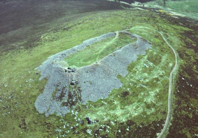
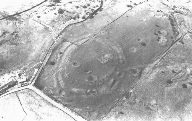

 The fort on Finavon Hill
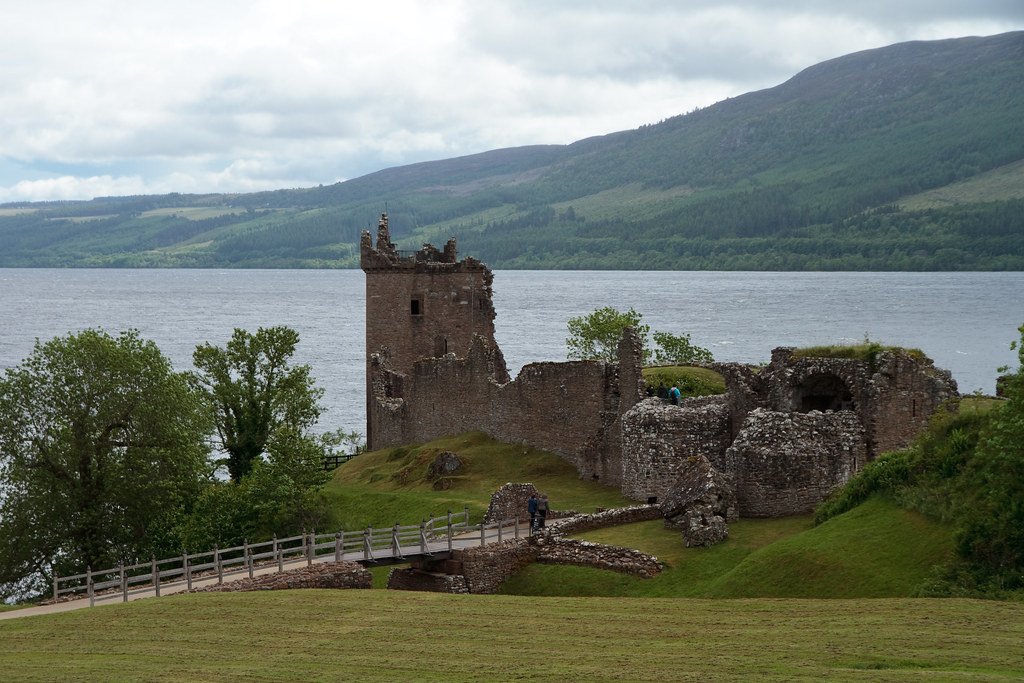 “
“